0 secondary modbus™ port, Secondary modbus™ port, Figure 29 non-protected vs. protected – Detcon 6400-N4X User Manual
Page 25: Figure 30 dip-switches, Ce, refer to section 7.0 secondary modbus™ port, Figure 30)
1600/6400-N4X
1600/6400-N4X- Instruction Manual
Rev. 1.1
Page 21 of 38
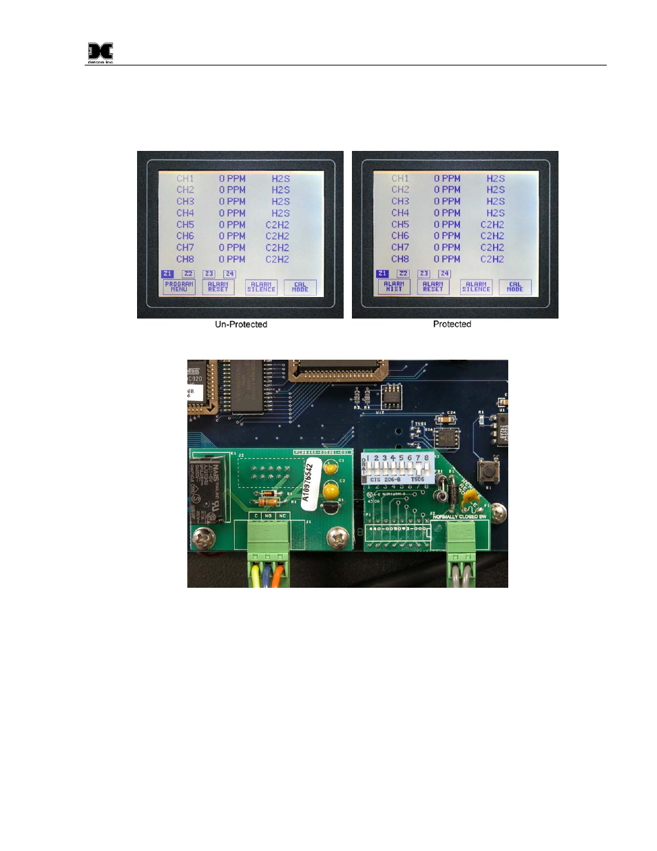
(Figure 29). This will allow the user to functionally operate the unit, but will not allow the user the capability
to change any important configuration parameters.
When switching between the Program Menu protected mode and unprotected mode, the user must press the
reset key on the back of the controller module to alert the controller to acknowledge the change in setting.
Figure 29 Non-Protected vs. protected
Figure 30 Dip-switches
7.0 Secondary Modbus™ Port
Model 1600/6400 controllers feature Modbus™ compatible communications protocols and are addressable by
a PLC, PC/HMI, DCS, or other Modbus™ RTU master polling device. Communication is accomplished by
two wire half duplex RS-485, 9600 or 19,200 baud, 8 data bits, 1 stop bit, no parity, with the 1600/6400
Controller secondary port setup as a slave device. Wiring should be brought directly to the back of the
controller (See section 3.0 and Figure 5). A Modbus™ RTU master device up to 4000 feet away can
theoretically poll up to 64 different controllers. This number may not be realistic in harsh environments where
noise and/or wiring conditions would make it impractical to place so many devices on the same pair of wires.
If a multi-point system is being utilized, each controller must be set to a different device address.