Figure 8 modbus™ gas sensor connections, Figure 9 model rl-4 relay module – Detcon 6400-N4X User Manual
Page 11
1600/6400-N4X
1600/6400-N4X- Instruction Manual
Rev. 1.1
Page 7 of 38
RS-485 Modbus™ Gas Sensors
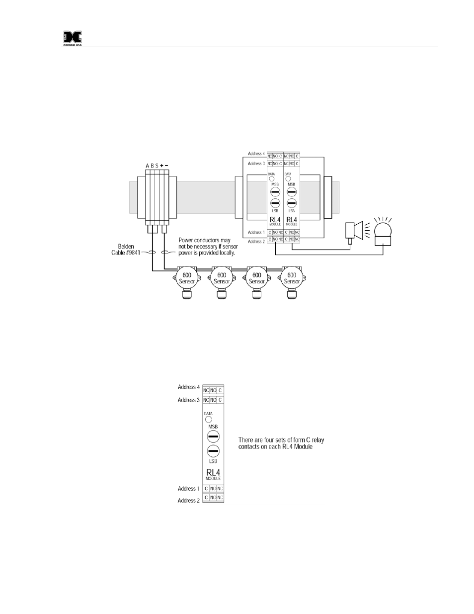
Connect the five wires from the Modbus™ gas sensors (Detcon Model 600 and Model 700 Series types) to the
din rail mounted terminals labeled RS-485 “A”, “B”, and “Shld” and VDC “+” and “-”. Note: the controller
power supply is only capable of handling 3-3.5Amps accumulative. If the external sensors plus the controllers
internal modules exceeds this rating, only three wires (RS-485 “A”, “B”, and “Shld”) should be used and a
remote DC power source should be utilized to provide DC power for the remote mounted gas sensors.
NOTE: A 120
Ω end of line resistor should be installed on the last gas sensor in the serial loop to enhance
communications reliability.
Figure 8 Modbus™ Gas Sensor Connections
Relay Output Contact Modules
There are four Form ‘C’ 5 Amp relay contacts in each Model RL4 module. These can be used to fire
annunciating devices or as signal inputs to other control devices. Connections to the relay contacts of the
Model RL4 module as shown in Figure 9. The amperage rating of the relay contacts should not be exceeded.
Figure 9 Model RL-4 Relay Module
4-20mA Output Modules
There are four 4-20mA outputs in each Model AO-4 module. These outputs can be used as signal inputs to
other control devices. Connection to the AO-4 modules as shown in Figure 10: