1 non-dispersive infrared (ndir) optical sensor, 2 microprocessor control circuit, Non-dispersive infrared (ndir) optical sensor – Detcon 1000_CO2 User Manual
Page 6: Microprocessor control circuit, Figure 2 ir cell construction, Figure 3 control faceplate
Model 1000 CO2
Model 1000 CO2 Instruction Manual
Rev. 2.2
Page 2 of 28
sensors feature field adjustable, fully programmable alarms and provide relays for two alarms plus fault as
standard. The sensor comes with two different outputs: analog 4-20mA, and serial RS-485. These outputs
allow for greater flexibility in system integration and installation. The microprocessor-supervised electronics
are packaged as a plug-in module that mates to a standard connector board. Both are housed in an explosion
proof condulet that includes a glass lens window, which allows for the display of sensor readings as well as
access to the sensor’s menu driven features via a hand-held programming magnet.
The sensor technology is a field proven “plug-in replaceable” non-dispersive infrared (NDIR) optical type.
NDIR optical sensors show an excellent response to CO
2
. The NDIR type sensor is characteristically stable
for both span and zero and is capable of providing reliable performance with low maintenance requirements
for periods approaching 5 years in most industrial environments.
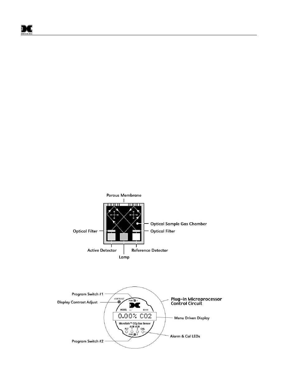
1.1.1 Non-dispersive infrared (NDIR) optical sensor
The Detcon NDIR sensor is designed as a miniature single piece “plug-in replaceable” component, which can
easily be changed out in the field. The NDIR sensor consists of an infrared lamp source, two pyroelectric
detectors, and an optical gas sample cavity. The lamp source produces infrared radiation, which interacts with
CO
2
as it travels through the optical gas sample cavity. The infrared radiation contacts each of two
pyroelectric detectors at the completion of the optical path. The “active” pyroelectric detector is cove red by a
filter specific to the part of the IR spectrum where CO
2
absorbs light. The “reference” pyroelectric detector is
covered by a filter specific to the non-absorbing part of the IR spectrum. When CO
2
is present, it absorbs IR
radiation and the signal output from the “active” pyroelectric detector decreases accordingly while the
“reference” detector output remains unchanged. The ratio of the “active” and “reference” detector outputs is
then used to compute CO
2
concentration.
Figure 2 IR Cell Construction
1.1.2 Microprocessor Control Circuit
Figure 3 Control Faceplate