3 electrical connections, Electrical connections, Figure 10 unit overview – Detcon 1000_CO2 User Manual
Page 11: Sensor
Model 1000 CO2
Model 1000 CO2 Instruction Manual
Rev. 2.2
Page 7 of 28
changes. An insertion probe membrane device is advisable to use for pipeline sources with high levels of
condensates, mist, and contamination.
2. Whenever possible, the Sample Bypass flow control valve of the Genie membrane filter should be used to
minimize the sample lag time between the sample tap and the analyzer location. It can also be used as a
means to exhaust condensed liquids in the sample line away from the Genie filter and prevent a “loss of
flow” condition. Set a flow of 100-200cc/min. and vent to a safe area using ¼ O.D. tubing. Connect the
tubing to the Over-Pressure Relief valve and vent to a safe area. The pressure relief valve is set at Detcon
to open at 15-20psig. For convenience, the sample bypass and over-pressure relief can be vented together.
SAMPLE
FLOW
INLET
SAMPLE
10 PSIG (CONSTANT)
SAMPLE PRESSURE
INLET
AIR
AIR
INLET
SAMPLE
OUTLET
SAMPLE
AIR
FLOW
MODEL NO.
SERIAL NO.
INPUT VOLTAGE
FREQUENCY
CURRENT LOAD
AREA CLASSIFICATION
detcon inc.
3200 A-1 Research Forest Dr.
The Woodlands, TX 77381
www .detcon.com
PART NO.
MODEL NO.
SERIAL NO.
INPUT VOLTAGE
FREQUENCY
CURRENT LOAD
AREA CLASSIFICATION
detcon inc.
3200 A-1 Research Forest Dr.
The Woodlands, TX 77381
www .detcon.com
PART NO.
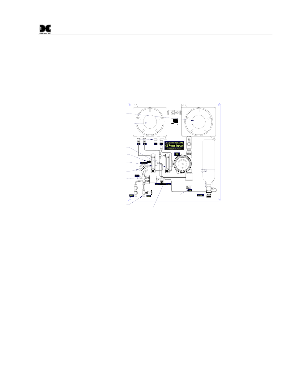
Over Pressure
Relief
Exhaust Vent
CO
2
3-Way Valve
Vent Port
CO
2
IR Sensor
NOTE: These can be combined into a single vent
Air Inlet Port
Sample Inlet Port
Sample Inlet
Pressure Gauge
CO
2
Sample or
Cal Gas Rotameter
Mass Flow Control
Air Flow Control
Rotameter
Flow Fault
and Pump Box
Power Supply Box
Figure 10 Unit Overview
3. Install a length of 1/4" OD stainless steel tubing from the vent port to an area deemed safe for venting as
shown below. The vent port should be separately vented from the over-pressure relief vent and the sample
by-pass vent.
3.3 Electrical Connections
1. For AC powered unit connect 110/220VAC to the terminal connector labeled “VAC IN” (JP8A) inside the
explosion-proof enclosure on the right. If applicable, connect 24VDC to the Terminal Connector Board
labeled “VDC IN” (JP7A). (Figure 11)
2. The 4-20mA and/or RS-485 signal outputs should be wired from the Terminal Connector Board and then
out the right side of the “Power Supply” explosion-proof enclosure. (Figure 11)
3. Alarm relay contacts are provided on the Terminal Connector Board for three alarms: Fault, Low, and
High (Figure 11). The contacts consist of common and choice of normally open or normally closed.
Contact output selections are jumper programmable on the sensor connector board. See IR-640/IR-642
wiring diagram for details. These connections also should be wired out of the right side of the “Power
Supply” explosion-proof enclosure (Figure 19). Sensor #1 termination corresponds to IR-640/IR-642 CO
2
Sensor.