0 gas flow and wiring diagrams, Gas flow and wiring diagrams, Figure 17 unit flow diagram – Detcon 1000_CO2 User Manual
Page 29
Model 1000 CO2
Model 1000 CO2 Instruction Manual
Rev. 2.2
Page 25 of 28
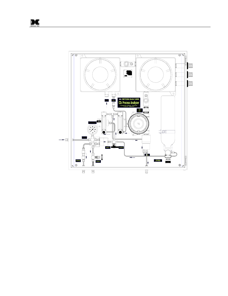
15.0 Gas Flow and Wiring Diagrams
SAMPLE
FLOW
AIR
FLOW
INLET
SAMPLE
10 PSIG (CONSTANT)
SAMPLE PRESSURE
INLET
AIR
AIR
MODEL NO.
SERIAL NO.
INPUT VOLTAGE
FREQUENCY
CURRENT LOAD
AREA CLASSIFICATION
detcon inc.
3200 A-1 Research Forest Dr.
The Woodlands, TX 77381
www.detcon.com
PART NO.
Sample
Input
SAMPLE CALIBRATE
Vent
Vent
Vent
Figure 17 Unit Flow Diagram
See also other documents in the category Detcon Equipment:
- 12B (16 pages)
- FL-10 (7 pages)
- 10C Facilities (18 pages)
- 10C (29 pages)
- 10B (10 pages)
- 1212-N4X (9 pages)
- 812-N4X (9 pages)
- 1212B (5 pages)
- 612B (5 pages)
- 1610-N4X (28 pages)
- 1010-N4X (14 pages)
- 610-N4X (12 pages)
- 1610-N1 (4 pages)
- 810-N1-24VDC (10 pages)
- 410-N1-24VDC (4 pages)
- MCX-32-N1P (55 pages)
- RD-64X-N4X (41 pages)
- 880RA-N4X (36 pages)
- 880RA-N4X (23 pages)
- 880A-N1R (45 pages)
- 880A-N4X (50 pages)
- 880A-N4X (43 pages)
- X40-08-N4X (70 pages)
- 240 (33 pages)
- SW-AV1-N4 (12 pages)
- SW-AV2-DV1 (12 pages)
- A1V1 (9 pages)
- RXT-300 (47 pages)
- RXT-320 (31 pages)
- CXT-N4X (28 pages)
- SW-HMI-32-N4X (24 pages)
- SW-V1-DV2 (11 pages)
- SW-AV1-DV1 (14 pages)
- SW-AV2-DV2 (12 pages)
- SW-AV1-DV2 (12 pages)
- SmartWireless CX (33 pages)
- SmartWireless CXT (49 pages)
- CX-IR (38 pages)
- CX-DM (44 pages)
- CXT-IR (48 pages)
- CXT-DM (56 pages)
- P-1000 (28 pages)
- 1000 (32 pages)
- 1000_H2S (34 pages)