0 operating software, 1 programming magnet operating instructions, 2 operating software – Detcon 1000_CO2 User Manual
Page 15: Operating software, Programming magnet operating instructions, Figure 14 programming magnet
Model 1000 CO2
Model 1000 CO2 Instruction Manual
Rev. 2.2
Page 11 of 28
NOTE: All alarms will be disabled for 1 minute after power up. In the event of power failure, the alarm
disable period will begin again once power has been restored.
NOTE: Sample flow rates are actual Rotameter set-point flow rates, after accounting for Rotameter gas.
5.0 Operating Software
5.1 Programming Magnet Operating Instructions
Operator interface to MicroSafe™ gas detection products is via magnetic switches located behind the
transmitter faceplate. DO NOT remove the glass lens cover to calibrate or change programming parameters.
Two switches labeled “PGM 1” and “PGM 2” allow for complete calibration and alarm level programming
without removing the enclosure cover, thereby eliminating the need for area de-classification or the use of hot
permits.
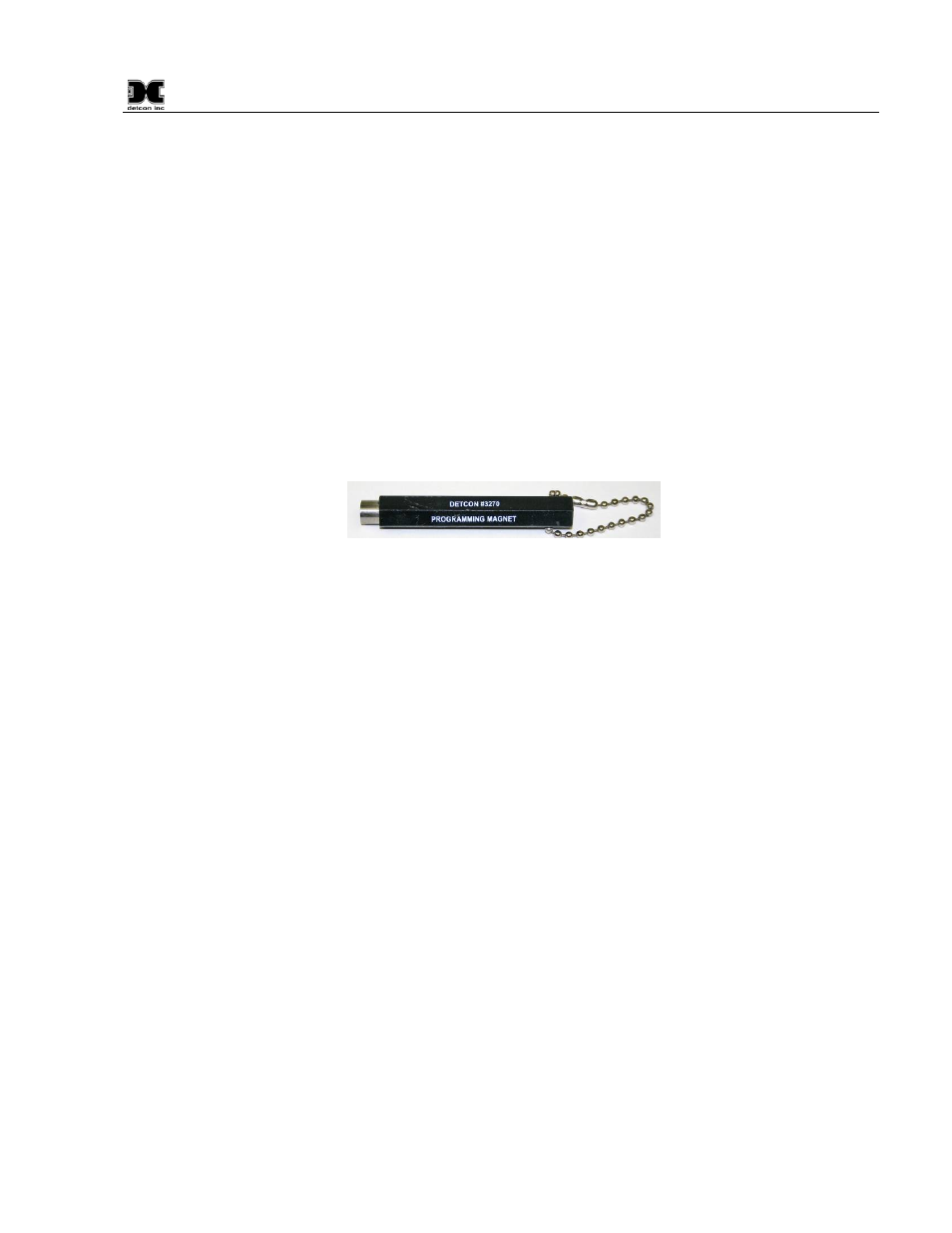
Figure 14 Programming Magnet
A magnetic programming tool (Figure 14) is used to operate the switches. Switch action is defined as
momentary contact, 3-second hold, and 30-second hold. In momentary contact use, the programming magnet
is waved over a switch location. In 3-second hold, the programming magnet is held in place over a switch
location for 3 or more seconds. In 30-second hold, the programming magnet is held in place over a switch
location for 30 or more seconds. Three and 30-second hold is used to enter or exit calibration and program
menus while momentary contact is used to make adjustments. The location of “PGM 1” and “PGM 2” are
shown in section 1.3.
NOTE: If, after entering the calibration or program menus, there is no interaction with the menu items for
more than 30 seconds, the sensor will return to its normal operating condition.
5.2 Operating Software
Operating software is menu listed with operator interface via the two magnetic program switches located under
the faceplate. The two switches are referred to as “PGM 1” and “PGM 2”. The menu list consists of 3 items
which include submenus as indicated below.
01. Normal Operation
a) Current Status
02. Calibration Mode
a)
Zero
b)
Span
03. Program Menu
a) Program Status
b) Alarm 1 Level
c) Alarm 2 Level
d) Calibration Level