4 relays and rs-485 setup, Relays and rs-485 setup, Figure 11 installation wiring connections – Detcon 1000_CO2 User Manual
Page 12: Figure 11), Figure 11). the c
Model 1000 CO2
Model 1000 CO2 Instruction Manual
Rev. 2.2
Page 8 of 28
AIR
FLOW
SAMPLE
FLOW
+
+
24VDC
OUT
2.1A
18-36
VDC
I N
+
+
24VDC
OUT
2.1A
18-36
VDC
IN
+
+
24VDC
OUT
2.1A
18-36
VDC
IN
4-20mA, RS485,
Alarm/Fault Sensor Relays
Low Flow Air/ Sample Relays
(Optional)
117VAC / 24VDC In
Customer Connections
+24VDC
-24VDC
(Ground)
INPUT
+
-
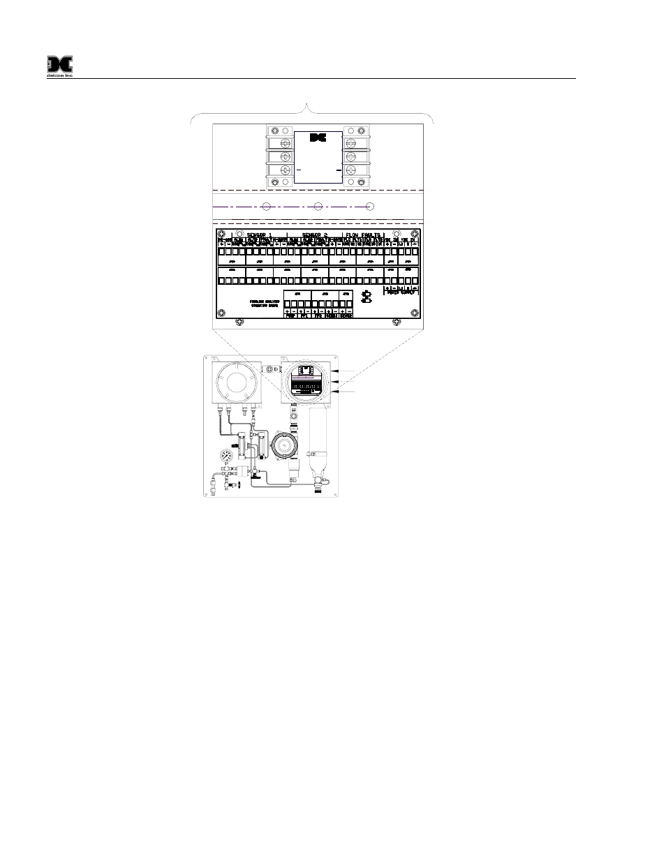
Figure 11 Installation Wiring Connections
4. Optional Low Flow Fault alarms for Sample gas and Air are also available on the Terminal Connector
Board (Figure 11). They provide a form “C” relay contact (common, normally open and normally closed)
rated 1 amp at 30 VDC/0.24 amps at 125 VAC. If the optional Air or Sample Flow Fault Boards are
installed the relay contacts are pre-wired to the Terminal Connector Board.
3.4 Relays and RS-485 Setup
Program the alarms via the gold plated jumper tab positions located on the CPU board (Figure 12). Alarm 1
and Alarm 2 have three jumper programmable functions: latching/non-latching relays, normally
energized/normally de-energized relays, and ascending/descending alarm set points. The fault alarm has two
jumper programmable functions: latching/non-latching relay, and normally energized/normally de-energized
relay. The default settings of alarms 1 and 2 (jumpers removed) are normally de-energized, non-latching
relays and alarm points that activate during ascending gas conditions. The Fault alarm default setting is de-
energized, latching. The relay Contacts which transferred from the Base Connector PCB to the Analyzer
Terminal Connector PCB are the Common and Normally Open (NO) contacts of the relays. These jumpers
reside on the Base Connector PCB (see Figure 4).