Detcon SmartWireless CX User Manual
Page 18
Sentinel CX
Sentinel CX Sensor Station IM
Rev. 1.4
Page 14 of 26
Figure 10 Attach Sensor Brackets to Tripod
6. Hang the sensors on the brackets using the hook and pin supplied with the bracket.
7. Connect sensor cables to the sensor ports on the CX (Figure 1).
8. If the unit is ordered with the optional external A1 C1D2 Horn, the horn should be mounted either
on the tripod, or on a separate tripod. . The optional A1 C1D2 Horn requires the cable for the
External ‘Wet’ Alarms.
a.
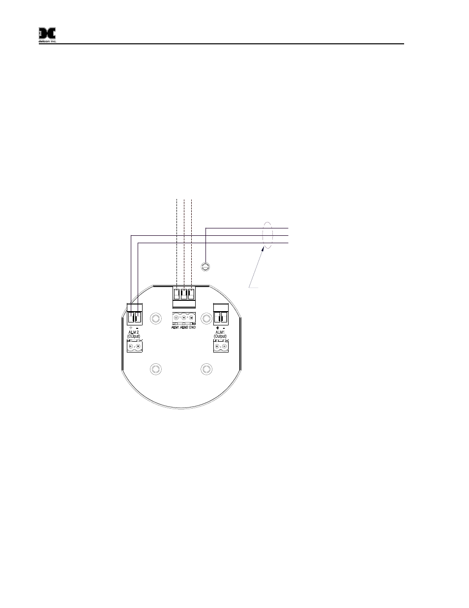
The horn should be wired to the ‘Wet’ Alarm Output cable per Figure 11.
b. The alarm Cable should be connected to the External Alarm Connector on the controller.
Red
Black
Green/Yellow
B
la
c
k
G
ra
y
Turck Alarm Cable
from Sentinel
C1D1 Cable Assembly
12-24 Alarm
Terminal PCA
W
h
it
e
To
Horn
Figure 11 A1 C1D2 Alarm Connections
Battery Installation
9. Loosen the screws holding the door panel in place, and swing the front door of the enclosure open
to gain access to the battery bracket.
- 12B (16 pages)
- FL-10 (7 pages)
- 10C Facilities (18 pages)
- 10C (29 pages)
- 10B (10 pages)
- 1212-N4X (9 pages)
- 812-N4X (9 pages)
- 1212B (5 pages)
- 612B (5 pages)
- 1610-N4X (28 pages)
- 1010-N4X (14 pages)
- 610-N4X (12 pages)
- 1610-N1 (4 pages)
- 810-N1-24VDC (10 pages)
- 410-N1-24VDC (4 pages)
- MCX-32-N1P (55 pages)
- RD-64X-N4X (41 pages)
- 880RA-N4X (23 pages)
- 880RA-N4X (36 pages)
- 880A-N1R (45 pages)
- 880A-N4X (43 pages)
- 880A-N4X (50 pages)
- X40-08-N4X (70 pages)
- 240 (33 pages)
- SW-AV1-N4 (12 pages)
- SW-AV2-DV1 (12 pages)
- A1V1 (9 pages)
- RXT-300 (47 pages)
- RXT-320 (31 pages)
- CXT-N4X (28 pages)
- SW-HMI-32-N4X (24 pages)
- SW-V1-DV2 (11 pages)
- SW-AV1-DV1 (14 pages)
- SW-AV2-DV2 (12 pages)
- SW-AV1-DV2 (12 pages)
- SmartWireless CXT (49 pages)
- CX-IR (38 pages)
- CX-DM (44 pages)
- CXT-IR (48 pages)
- CXT-DM (56 pages)
- P-1000 (28 pages)
- 1000 (32 pages)
- 1000_CO2 (32 pages)
- 1000_H2S (34 pages)