Power switch, Power connector, Remote i/o cabling accessory and safe use – Detcon SmartWireless CX User Manual
Page 12: Figure 8 power connector, 8 power switch, 9 power connector, 10remote i/o cabling accessory and safe use
Sentinel CX
Sentinel CX Sensor Station IM
Rev. 1.4
Page 8 of 26
1.8 Power Switch
Power to the SmartWireless® CX is controlled by a power switch located on the bottom of the enclosure
(Figure 1). Pressing this switch while the power is off will turn the CX on. Pressing the switch while the
power is on will turn the power off. When the power to the CX is on, the green LED indicator on top of the
enclosure will be illuminated.
1.9 Power Connector
The internal battery inside the SmartWireless® CX Sensor Station can be recharged by connecting 24VDC
to the power connector on the side of the enclosure (Figure 1). A VAC/24VDC battery charging adapter is
included with every CX.
Detcon Approved Battery Charger Accessory Ratings:
AC Input Power
Voltage: 100-240 VAC, 50-60 Hz (requires correctly selected 110 VAC or 220 VAC Charger)
Current: 2.0 Amps maximum
DC Output Power
Voltage: 24+/- 1 VDC
Current: 3.1 Amps maximum
CAUTION
The SmartWireless® CX Sensor Station must be charged with the Detcon supplied
Battery Charger. (Detcon P/N: 976-0003BC-00T for 110VAC and P/N 976-
0003BC-220 for 220VAC ). Use of any other charger may damage the controller.
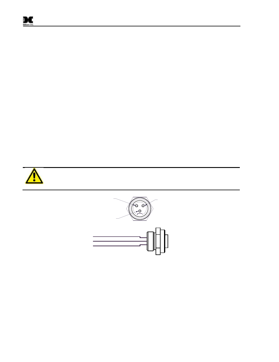
GND
(Black) 2
+24VDC
(White) 3
Chassis GND (Green) 1
Pin 1
Pin 2
Pin 3
Figure 8
Power Connector
1.10Remote I/O Cabling Accessory and Safe Use
The I/O cabling option designed for the CX Sensor Station and its safe use is described in the cabling
Speciation section in Section 9.1. A specific list of Detcon approved cabling option lengths are given in the
Spare Parts List.
Security clips, which require a tool for removal, are provided and are required for all I/O Turck connector
based cables. All Turck connectors should have the security clip engaged at all times except for when
disconnecting them in the safe area.