3 model 100 terminal board (optional) – Detcon RXT-320 User Manual
Page 7
RXT-320 Wireless Modbus
™
RXT-320 Wireless IM
Rev. 2.1
Page 3 of 27
NOTE: If there are multiple Modbus™ networks in the same vicinity each system must reside
on a different RF Channel to keep data from one appearing on the other.
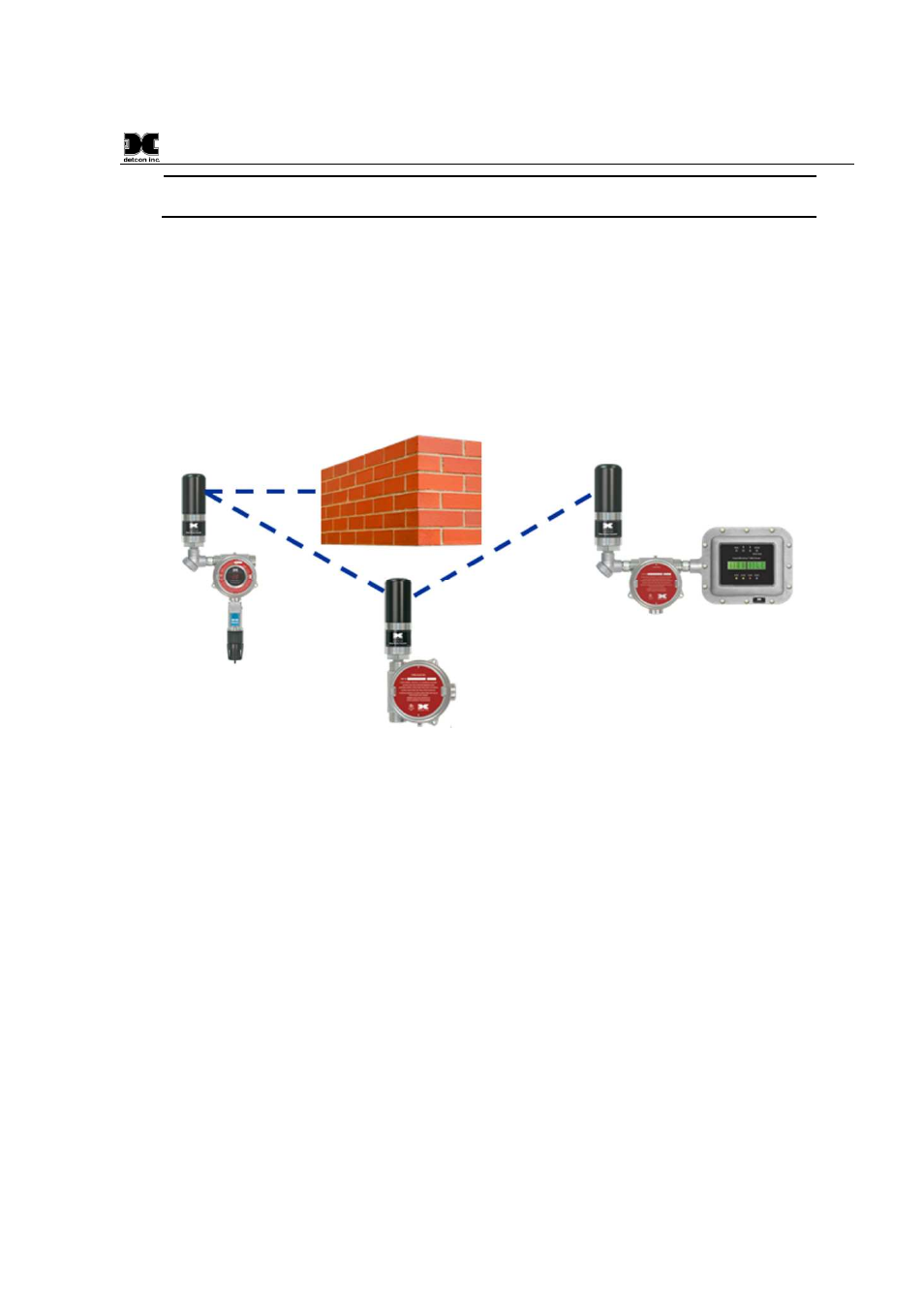
The 802.15.4 standard also implements a mesh network allowing any RXT-320 transceiver to relay or repeat
data between adjacent neighbors. This makes the network very robust and provides the following immediate
benefits:
Allows re-routing of data in case of loss of a transceiver
Allows re-routing around wireless obstacles
Longer distances between transceivers because data can “hop” from one transceiver to the next
Included in sensor, controller and alarm station transceivers
RXT-320 transceivers can be deployed with less concern about physical location
Figure 3 Mesh Network Topology
1.3
Model 100 Terminal Board (Optional)
The RXT-320 wireless transceiver can be ordered with an optional Model 100 Terminal Board mounted in a
condulet/J-Box (See Figure 4). The terminal board includes connector plugs for the following:
J1 6-Pin Phoenix Connector – RXT-320 Wireless Transceiver
J2 5-Pin Phoenix Connector – Slave Device/Master Controller/Remote Monitor
J3 6-Pin Connector – RXT Programming Port (Detcon Factory use only)
J4 3-Pin Phoenix Connector – Model 100 Loop Powered LED display
J5 3-Pin Phoenix Connector – 7-30VDC External power source or 24VDC Solar Panel
J6 8-Pin Beau Connector – 12VDC Battery Power (Use only Detcon’s Smart Battery Pack)
J7 3-Pin Phoenix Connector – Spare Modbus™ Connection
J8 3-Pin Phoenix Connector – RXT Programming Interface to Wireless Transceiver
Refer to section 2.4 for more information about the setup of the Model 100 Terminal Board.