0 introduction, 1 description – Detcon RXT-320 User Manual
Page 5
RXT-320 Wireless Modbus
™
RXT-320 Wireless IM
Rev. 2.1
Page 1 of 27
1.0
Introduction
1.1
Description
The RXT-320 wireless transceiver is designed to take Modbus™ communication between devices to a
wireless platform. The transceiver connects directly to a Modbus™ device and transfers Modbus™ data
to/from the device through the transceiver’s wireless radio.
The transceiver broadcasts this information
throughout a wireless network of other RXT-320 transceivers connected to Modbus™ devices thus creating a
seamless network of Modbus™ devices that need not be physically connected in any way. The RXT-320
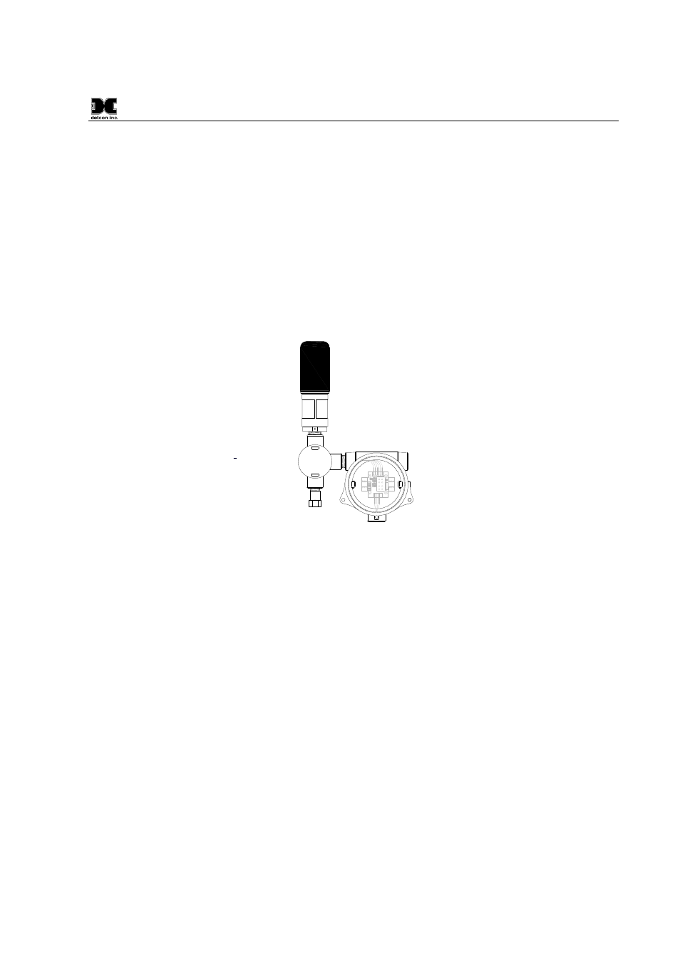
transceiver can be mounted to a J-Box/condulet with an optional Model 100 Terminal Board that allows for
power, data connections and addressing enabling it to interface with a wide range of devices. Refer to Figure
1 for a typical wireless transceiver assembly.
SENSOR/
HMI
R BK W BU GN
J2
BU W BK R
W/
W/
BR
BK
WIRE-
LES S
J1
J4
J6
J8
J3
TP2
mA
-
+
+
-
SA
WB WA SB
J7
T
P
1
1 2 3
2
3
4
5
6
7
1
External DC
Power In
7-30VDC
Spare Modbus
RXT-320 Transceiver
Slave Device/
Master Controller/
Rem ote Monitor
RXT Prog
Interface
R
X
T
P
ro
gr
am
m
in
g
P
o
rt
J5
Smart Battery Pack
W/
BU
W/
GN
W/V
Loop Powered
LED Display
RXT-320 Wireless Transceiver
J-Box w/
Model 100
Terminal Board
3
4
" NPT T-Outlet
Box w/Drain
Figure 1 RXT-320 Wireless Transceiver Assembly
The RXT-320 wireless transceiver provides interfaces for 4-20mA devices as well as Modbus™ devices.
There can be up to 32 devices total on a single wireless network and a transceiver can support more than one
device. Additionally, there can be up to 32 RXT-320 transceivers in a single wireless network. The RXT-320
transceiver’s radio operates at 2.4GHz and conforms to non-licensed radio frequency appliance usage around
the world. Wireless network integrity and security is accomplished using Direct Sequence Spread Spectrum
(DSSS) wireless mesh technology. Each transceiver is capable of functioning as a router or repeater for all
other RXT-320 transceivers on the network.
This means that data between devices can “hop” through
neighboring transceivers to communicate with each other thereby widening network access points.
This
unique and innovative technology is designed to create a robust network that automatically routes around
congestion and line-of-sight obstacles while improving throughput as the number of devices increases.
The RXT-320 transceiver comes equipped with an RS-485 port for communication with local Modbus™
devices. As with normal Modbus™ operation, there can only be one Modbus™ master and all other devices
are considered as slave devices. Each device must have a unique Modbus™ address. Each transceiver is also
assigned a Modbus™ address via the Model 100 Terminal Board which has two rotary switches used to set the
address.
The Modbus™ master unit’s transceiver is responsible for broadcasting requests and receiving slave device
responses. Slave device transceivers receive these broadcasts and pass the Modbus™ information on to the
slave devices attached via their local Modbus™ interface. When a response is generated by the slave device, it
sends it back to its transceiver through the Modbus™ interface.
The transceiver then broadcasts that