0 operation and configuration, 1 transparent mode – Detcon RXT-320 User Manual
Page 20
RXT-320 Wireless Modbus
™
RXT-320 Wireless IM
Rev. 2.1
Page 16 of 27
NOTE: If using a Smart Battery Pack, battery pack removal is required to access the
rotary switches for Modbus™ addressing and to access the board jumpers.
Assigning a Modbus™ address to the transceiver allows registers within the transceiver itself to be accessed
by the master and provide additional control and status from that transceiver. Using these registers, the master
controller can control alarm outputs, read the two 4-20mA inputs, read battery life or put the network to sleep
to conserve battery.
The address also determines the mode of operation for the transceiver.
This will
determine if it is attached to a master controller or if it is attached to a slave device.
3.0
Operation and Configuration
The RXT-320 wireless transceiver assembly will power up as soon as power is applied. There is no external
power switch to the assembly.
NOTE:
Before applying power, check to make sure that all the wiring connections and
external devices are installed correctly.
NOTE:
Applying power with devices hooked up incorrectly may cause damage to the
equipment.
The user will need to manually configure the Modbus™ address for the RXT-320 from the Model 100
Terminal Board. If there is no Model 100 Terminal Board, the transceiver will have no address and function
in transparent mode.
After the transceiver has been configured and powered up, it will begin normal
operation. If the unit has been configured properly, the unit will operate differently based on the address given
from the terminal board which is read once every five seconds using the I
2
C interface.
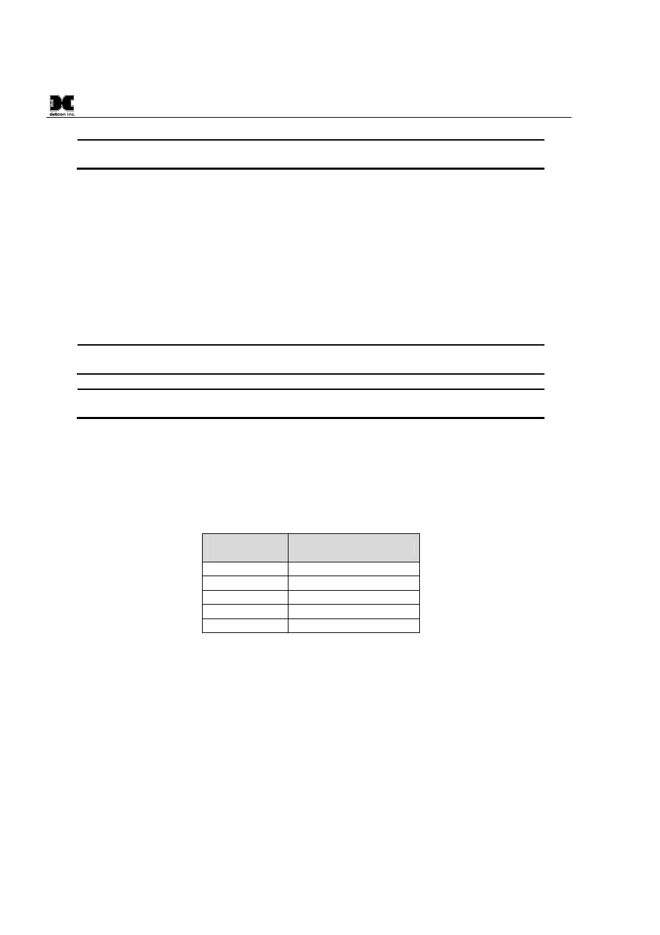
Table 5 RXT-320 Addressing and Operational Modes
Modbus
Address (hex)
RXT-320 Function
00
Transparent Mode
F0
Master
01-7F, 90-DF
Slave
80-8F, E0-EF
Alarm Station
F8-FF
Reserved per Modbus™
3.1
Transparent Mode
In transparent mode, the RXT-320 wireless transceiver behaves like a wired Modbus™ device in that any data
transmitted over Modbus™ will be passed on over the RF network and be broadcast to all other RXT-320’s in
the wireless network and presented on their respective Modbus™ interface. The transparent mode is achieved
by setting the transceiver’s Modbus™ address equal to 00h through the transceiver’s terminal board. If the
Model 100 Terminal Board is not installed, the transceiver will default to an address of 00h. The transceiver
will behave as neither a master nor slave and its internal RXT-320 registers can not be accessed. Any devices
connected to a transceiver in transparent mode will receive all controller requests via the Modbus™ interface
and a response by the device will occur only if its Modbus™ address is equal to the request address. If so, the
device will respond back to the transceiver via Modbus™ which will then send the response back to the
controller over the RF network.