4 4-20ma a & b – Detcon RXT-320 User Manual
Page 18
RXT-320 Wireless Modbus
™
RXT-320 Wireless IM
Rev. 2.1
Page 14 of 27
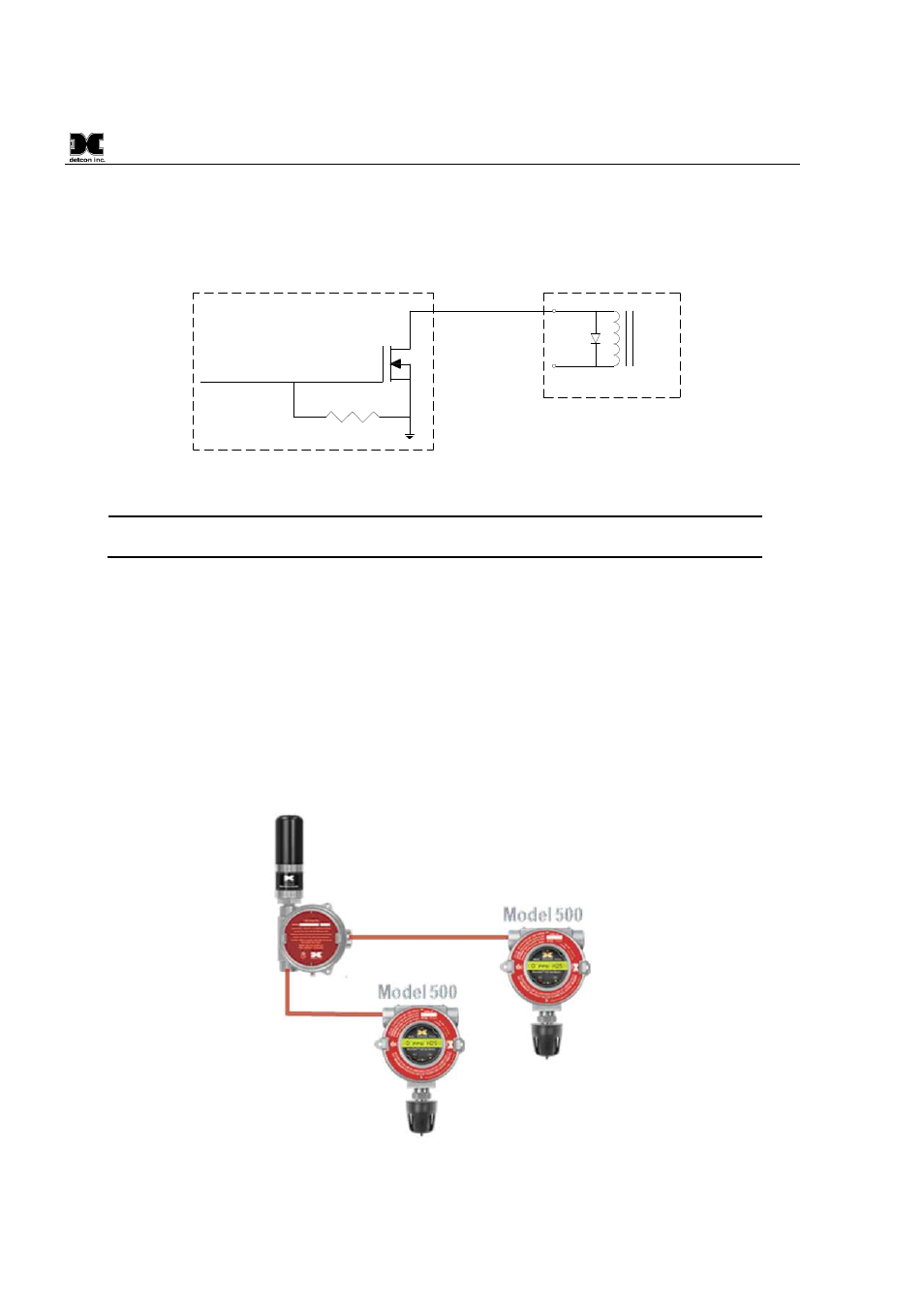
provide a complete solution to connecting an RXT-320 to power and providing high-current relay closures.
When using interposing relays, it is strongly recommended to install a transient protection diode (1N4001)
across the relay coil to mitigate the voltage spike when the coil is de-energized.
49.9K
RXT-320
Relay
Coil
Alarm Output
V+
1N4001
Diode
MOSFET N-CH
50V 300mA
From RXT-320
Processor Output
Interposing Relay
Figure 12 Internal Alarm Output Circuit
NOTE: External relays used with this circuit must not exceed voltage/current requirements
and must have transient protection to minimize the voltage spike when the coil is de-energized.
2.3.4
4-20mA A & B
The RXT-320 supports up to two 4-20mA signal inputs (A and B) used for monitoring 4-20mA devices (See
Figure 13). For the primary 4-20mA signal input, use A (green wire). For the secondary 4-20mA signal input,
use B (yellow wire). The input values are continuously read and stored in two separate registers accessible
through Modbus™ at the address assigned to the transceiver. Readings on a 4-20mA input are converted to
representative values, for example, 4mA is read as a value of 400 and 20mA is read as a value of 2000. These
inputs present a load of 162 ohms to ground so a current of 20mA will develop around 3.4V across the input
and ground. This will consume a third less power versus the 250 ohm load used in other implementations.
The inputs are protected for voltages up to 30V but the input reading will reach a maximum of 2048 for
currents greater than 20mA. Electrically the 4-20mA interface supports 2-wire and 3-wire devices.
Figure 13 Up to two Sensors using two 4-20mA Interfaces