Detcon RXT-320 User Manual
Page 13
RXT-320 Wireless Modbus
™
RXT-320 Wireless IM
Rev. 2.1
Page 9 of 27
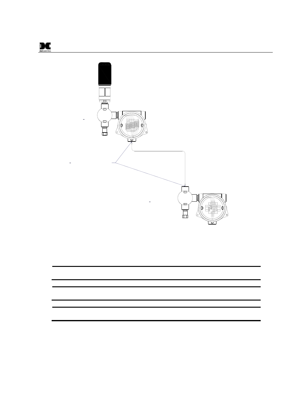
Power, Modbus & I²C
Remote RXT-320 Wireless Transceiver
Extension Cable to/from
Remote RXT Transceiver
Up to 15' Length
J-Box w/
Model 100
Terminal Board
Remote J-Box w/
8-Position
Terminal Board
3
4
" NPT Cord Connectors
(Cable Glands) Required
SENSOR/
HMI
R BK W BU GN
J2
BU W BK R
W/
W/
B R
BK
WIRE-
LESS
J1
J4
J6
J8
J3
TP2
m A -
+
+
- SA
WB WA SB
J7
TP
1
1 2 3
2
3
4
5
6
7
1
External DC
P ower In
7-30VDC
Spare ModBus
RXT-320 Transceiver
Slave Device/
Master Controller/
Remote Monitor
RX T Prog
Interface
Loop Powered
LED Display
R
XT
Pr
og
Po
rt
(
D
et
co
n
Us
e
O
nl
y)
J5
Smart Battery Pack
W/
B U
W/
GN
W/V
3
4
" NPT T-Outlet
Box w/Drain
Remote
3
4
" NPT
T-Outlet Box w/Drain
Figure 10 RXT-320 Wireless Transceiver Remote Mounting
A custom extension cable needs to be built per Figure 11 to interface the remote transceiver to the Model 100
Terminal Board.
The recommended cable for remote transceiver separation is Belden 1421A (24AWG
shielded twisted pair, 4 pairs w/drain wire).
NOTE: It is highly recommended to install the extension cable inside rigid metal conduit to
eliminate potential EMI and RFI interference and to maintain a Class I Division I rating.
NOTE: Color coding of the cable will no longer match the color coding on the Model 100
Terminal Board for the J1 connector.
NOTE:
Programming of RXT transceiver from the Model 100 Terminal Board will be
disabled.