2 modbus™ a & b, 3 alarm 0-3 – Detcon RXT-320 User Manual
Page 17
RXT-320 Wireless Modbus
™
RXT-320 Wireless IM
Rev. 2.1
Page 13 of 27
If an external power source is installed, the RXT-320 wireless transceiver requires two conductor connections
for the power supply. External DC power can be customer provided with an output voltage range between 7 to
30VDC or by Detcon’s optional 24VDC solar charging panel.
Both of these alternatives will provide
continuous operation of the assembly and can be installed in conjunction with the optional battery pack,
providing a constant power source. The external power supply will also maintain the battery pack fully
charged with no overcharging issues to be concerned with due to the battery pack’s “smart” circuitry. In this
configuration, external charging of the battery pack will not be necessary. In the event the external power
fails, the battery pack will continue to power the wireless transceiver assembly until external power is restored
or the battery is discharged.
If the Model 100 Terminal Board option is not used, power to the transceiver should be directly applied to its
red and black wires accordingly. If the terminal board is used, wiring designations for power are ‘+’ and ‘-’
(External DC Power In) on the J5 connector of the Model 100 Terminal Board. The maximum wire length
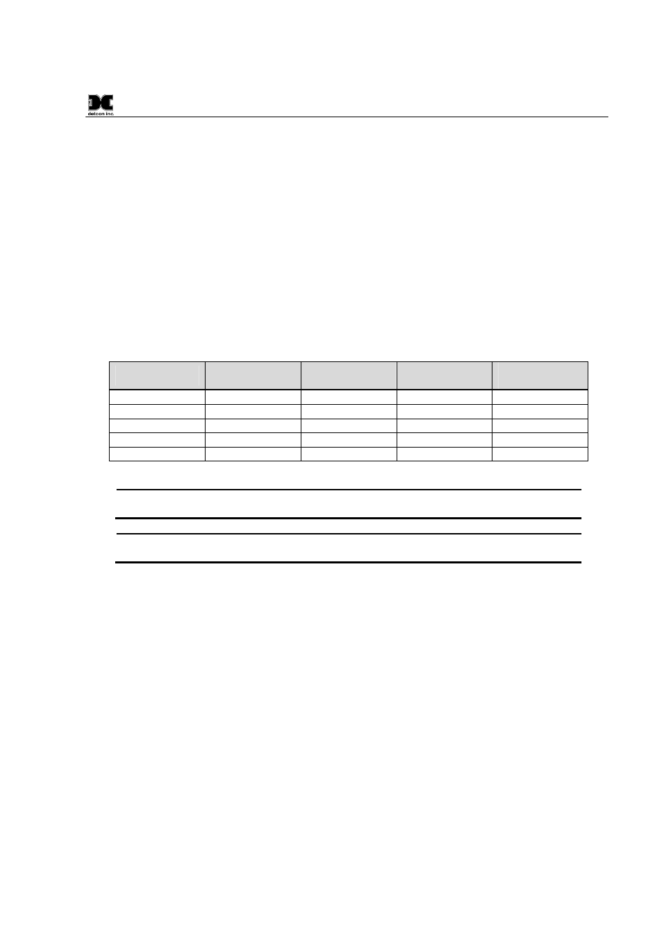
between the transceiver assembly and a 24VDC source is shown in Table 3 Wire Gauge vs. Distance. The
maximum wire size for termination in the J-Box is 14 AWG.
Table 3 Wire Gauge vs. Distance
AWG
Wire Dia.
Meters
Feet
Over-Current
Protection
22
0.723mm
700
2080
3A
20
0.812mm
1120
3350
5A
18
1.024mm
1750
5250
7A
16
1.291mm
2800
8400
10A
14
1.628mm
4480
13,440
20A
NOTE: Wiring table is based on stranded tinned copper wire and is designed to serve as a
reference only.
NOTE: The supply of power should be from an isolated source with over-current protection
as stipulated in table. The output voltage range must be between 7-30VDC.
Before applying power, make sure that all wiring is correct. Not all wires from the wireless transceiver are
used in most configurations. Wires that are not used should be individually capped off and secured out of the
way in the T-Outlet that mounts the transceiver to the J-Box/condulet. This prevents exposure to any active
components, power or ground.
2.3.2
Modbus™ A & B
The RXT-320 transceiver features a Modbus™ compatible communication port. The connections are
Modbus™ A (blue wire) and Modbus™ B (white wire) and are polarity dependent.
Modbus™
communication is accomplished by two wire half duplex RS-485, 9600 baud, 8 data bits, 1 stop bit, no parity,
through the transceiver’s connection to the Modbus™ device. It is necessary to set a Modbus address for the
RXT-320 unless operating in transparent mode.
2.3.3
Alarm 0-3
Each RXT-320 wireless transceiver provides outputs for up to four alarms (Alarm 0, Alarm 1, Alarm 2 and
Alarm 3) which can drive relays on custom terminal boards provided by Detcon. There are four internal
Modbus™ registers that directly control these outputs. The outputs are open drain and rated for up to 300mA
at 50V (See Figure 12). They are not intended to drive alarm devices directly, but rather to drive relay coils
(interposing relays) which in turn will drive a higher current output.
Detcon alarm terminal boards are
available that allow either AC or DC/Battery operation with the relays built onto the board. These boards