5 serial clock & serial data line, 6 programming data, clock & reset, 4 model 100 terminal board settings – Detcon RXT-320 User Manual
Page 19
RXT-320 Wireless Modbus
™
RXT-320 Wireless IM
Rev. 2.1
Page 15 of 27
NOTE: The 4-20mA inputs do NOT support 4-wire implementations
2.3.5
Serial Clock & Serial Data Line
This is the I
2
C interface for the transceiver consisting of a serial clock (SCL) and serial data line (SDA). These
are used to monitor the status of the battery pack (if installed) and to read the value of the Modbus™ address
switches of the Model 100 Terminal Board (if installed).
2.3.6
Programming Data, Clock & Reset
These connections are used to program the RXT-320 transceiver and should be used by Detcon personnel
only.
2.4
Model 100 Terminal Board Settings
This section applies to transceiver assemblies that use the optional Model 100 Terminal Board. This terminal
board contains a set of jumpers that must be configured properly for the board to operate properly. These
jumpers are normally configured at the factory and should not be changed. Misplacement of these jumpers
may cause the transceiver to become inoperative. The following table describes the jumper positions.
Table 4 Model 100 Terminal Board Jumper Settings
Jumper
Setting
JP1
2-3
JP2
1-2
JP3
1-2
JP4
1-2
JP5
2-3
JP6
1-2
JP7
1-2
NOTE: These settings assume the RXT-320 is not being used with a Detcon Model 100
sensor. If the RXT-320 is being used with a Model 100 sensor, these jumper settings may be
different. Please refer to the appropriate Model 100 manual for the correct settings.
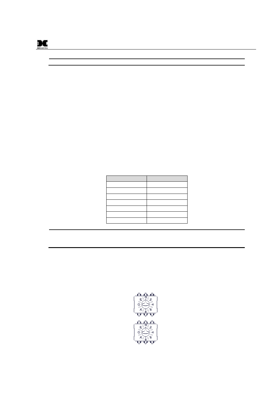
The Model 100 Terminal Board also contains two rotary switches which are used to set the Modbus™ address
for the RXT-320 wireless transceiver. The address selected is a two digit hex value with the MSD (most
significant digit) represented by the top rotary switch (closest to the J1 connector) and the LSD (least
significant digit) represented by the bottom rotary switch (closest to the J2 connector). For example, a hex
value of ‘9F’ would be represented by a ‘9’ on the top switch and an ‘F’ on the bottom switch.
Figure 14 Model 100 Terminal Board Rotary Switches