3 wiring connections / functions, 1 vdc power & vdc return – Detcon RXT-320 User Manual
Page 16
RXT-320 Wireless Modbus
™
RXT-320 Wireless IM
Rev. 2.1
Page 12 of 27
NOTE:
Programming of RXT transceiver from the Model 100 Terminal Board will be
disabled.
15. Plug battery pack back in place and reinstall the J-Box cover from step 1.
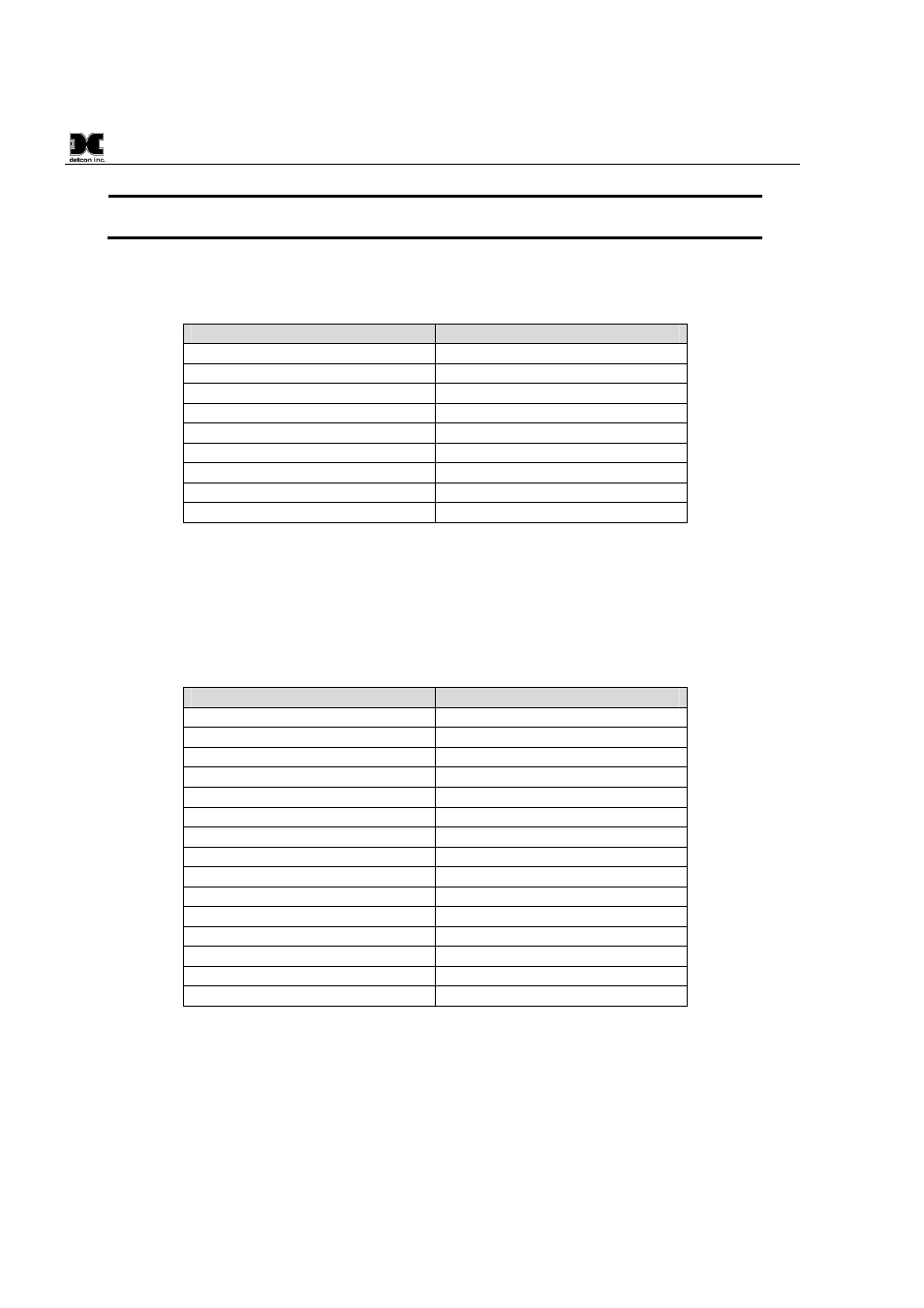
Table 1 Extension Cable Wire Identification
Function
Color Reference
VDC Power (+)
Orange/White
VDC Return (-)
Green/White
Modbus A (+)
Blue/White
Modbus B (-)
White/Blue
Serial Clock (SCL)
White/Green
Serial Data Line (SDA)
White/Brown
Common Ground
White/Orange
Common Ground
Brown/White
Drain Wire
Bare (No Color)
2.3
Wiring Connections / Functions
Dependant upon use and function, the RXT-320 wireless transceiver can be wired in different ways to
different devices. It is important to insure that the wiring is correct for the device to operate properly. Wire
identification for the transceiver can be found in Table 2 RXT-320 Transceiver Wire Identification.
Table 2 RXT-320 Transceiver Wire Identification
Function
Color Reference
VDC Power (+)
Red
VDC Return (-)
Black
Modbus™ A (+)
Blue
Modbus™ B (-)
White
Alarm 0
Brown
Alarm 1
Orange
Alarm 2
Violet
Alarm 3
Gray
4-20mA A
Green
4-20mA B
Yellow
Serial Clock (SCL)
White/Black
Serial Data Line Data (SDA)
White/Brown
Programming Data
White/Green
Programming Clock
White/Blue
Programming Reset
White/Violet
2.3.1
VDC Power & VDC Return
All RXT-320 wireless transceivers need to have DC power applied to the transceiver’s red (VDC power) and
black (VDC return) wires. The power requirements for the transceiver are such that the DC voltage input
range is 7 to 30 volts. This power will normally be supplied by the device the transceiver is connected to, but
can come from alternate DC sources such as the optional Smart Battery Pack, solar panel or external customer
supplied DC source.