1 register – detcon type, 2 register – alarm outputs – Detcon RXT-320 User Manual
Page 25
RXT-320 Wireless Modbus
™
RXT-320 Wireless IM
Rev. 2.1
Page 21 of 27
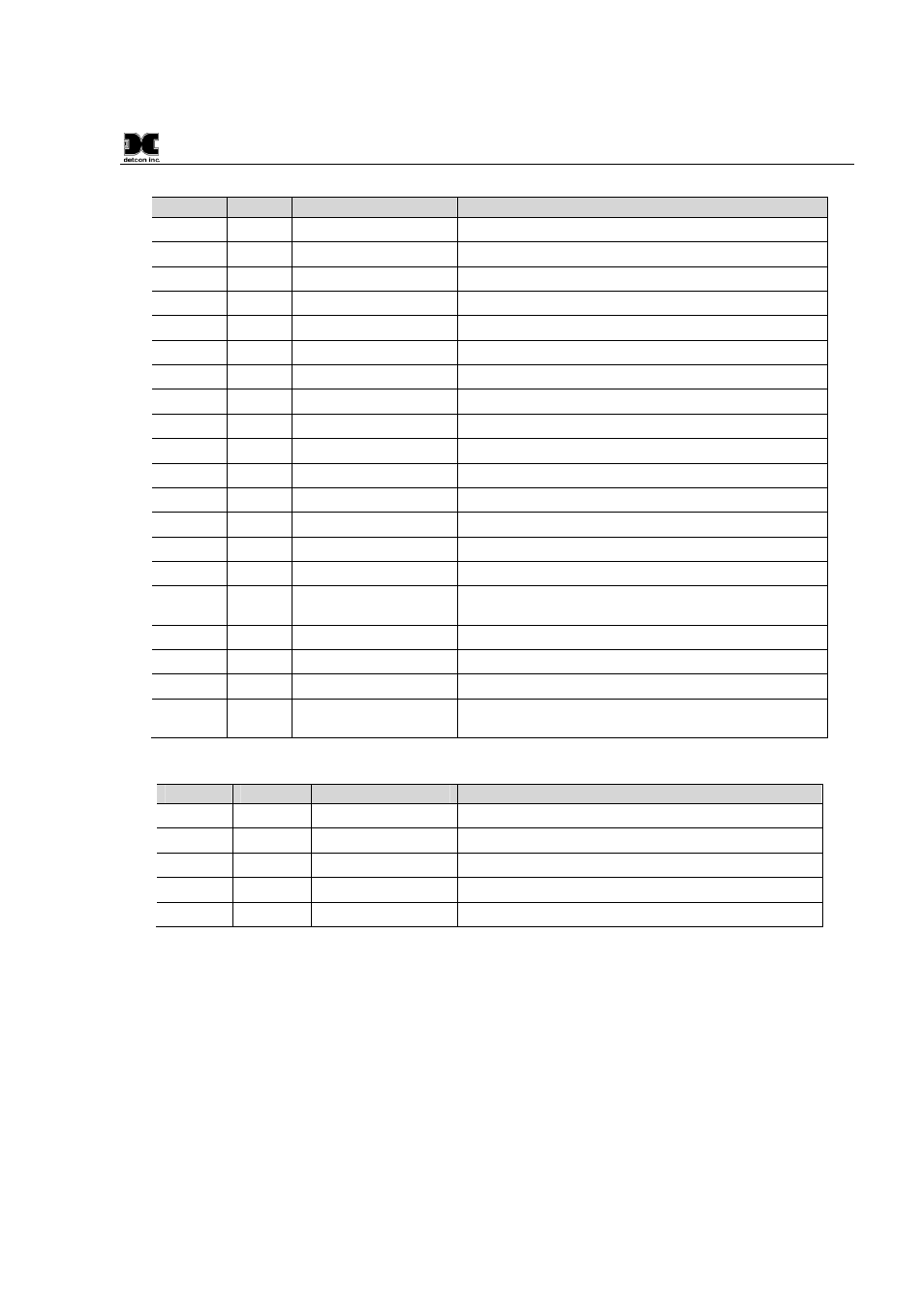
Table 7 RXT-320 Register Map
Register
Access
Name
Description
8192
R
Detcon Type
Detcon Register Type = 22 for RXT-320
8193
R/W
Alarm 0 Output
Controls the Alarm 0 Output
8194
R/W
Alarm 1 Output
Controls the Alarm 1 Output
8195
R/W
Alarm 2 Output
Controls the Alarm 2 Output
8196
R/W
Alarm 3 Output
Controls the Alarm 3 Output
8197
R
4-20mA A
Reading for 4-20mA Sensor Input (A)
8198
R
4-20mA B
Reading for 4-20mA Sensor Input (B)
8199
R
Battery Life Percent
Battery Life remaining in %
8200
R
Battery Life Minutes
Battery Life remaining in minutes
8201
R
uC Version
Micro Controller Firmware Version (Major.Minor)
8202
R/W
Sleep Time
Sleep Time in seconds
8203
R/W
Control
RXT-320 Control register
8204
R
Status
Status
8205
R
Battery Voltage
Battery Voltage in millivolts
8206
R/W
I2C Batt Read Fails
I
2
C Battery Read failure count
8207
R/W
I2C Switch Read
Fails
I
2
C Rotary Switch Read failure count
8208
R
Timestamp Secs High
Time from Startup – Seconds High
8209
R
Timestamp Secs Low
Time from Startup – Seconds Low
8210
R
Timestamp mSecs
Time from Startup -- Milliseconds
8211 –
8270
--
Reserved
Reserved registers
Table 8 RXT-320 Secondary Alarm Output Register Map
Register
Access
Name
Description
0000
R
Detcon Type
Detcon Register Type = 03 for RL4
0001
R/W
Alarm 0 Output
Controls the Alarm 0 Output
0002
R/W
Alarm 1 Output
Controls the Alarm 1 Output
0003
R/W
Alarm 2 Output
Controls the Alarm 2 Output
0004
R/W
Alarm 3 Output
Controls the Alarm 3 Output
4.2.1
Register – Detcon Type
Both register maps include this Detcon Type and is a unique identifier of the type of device and associated
register map. A controller can therefore perform a search and determine what Detcon devices are present on a
Modbus™ system.
4.2.2
Register – Alarm Outputs
There are four registers that control the four open collector Alarm Outputs. A value of 0 written to these
register will turn the Alarm Output off (not grounded). A value of 1 or non-zero value will turn the Alarm
Output on (grounded). If the secondary Alarm Output registers are enabled, the registers are duplicated and
writing to either set will turn on or off the Alarm Outputs. The current value of the Alarm outputs can be read
at any time. The default value for all Alarm Outputs upon power up or reset is 0.