3 programmable logic controller, Direct, 4 isolated network adapter – Detcon 880S-N4X User Manual
Page 8: Figure 4 basic plc
880-N4X
880-N4X Instruction Manual
Rev. 1.0
Page 4 of 40
The touch panel acts as a master interface to the internally located PLC. As such, the touch panel polls the
PLC, which, in turn, polls the field devices for information. A wand is used on the screen to operate system
controls and/or move to additional screens.
A USB port (Figure 3) is located on the back of the display at the bottom. When a USB Drive (USB Memory
Stick) is installed, the display will automatically log to the drive when any alarms and/or faults have been
recorded by the PLC. The information is logged into a folder named ‘Log’ and named ‘Alarm_yymmdd.txt’
where yy is the year, mm is the month, and dd is the day. The files are written in text format.
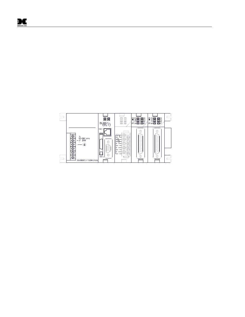
2.3 Programmable Logic Controller
At the core of the Model 880 is the modular Programmable Logic Controller (PLC), which is designed to offer
maximum flexibility in system configuration (Figure 4). The PLC and all other electronic components are
mounted within the enclosure.
G
+
Direct
LOGIC
205
PWR
BATT
STOP
RUN
TERM
CPU
RUN
CPU
RELAY
4
5
7
6
1
3
2
0
D2-08TR
OUT
RELAY
7
3
6
2
5
1
4
0
C
C
5-240VAC
1A 50/60Hz
5-30VDC
5mA-1A
L
L
D2-DCM
DATA
COM
D2-DCM
DATA
COM
Figure 4 Basic PLC
Installed in the PLC is the programmable Central Processing Unit (CPU), which processes all instructions,
data, and polls all field devices. The CPU utilizes flash memory to store the running program. All units are
shipped with firmware loaded and a lithium battery installed. The CPU has two communication ports. The
top RS232 port (Port 1) is the programming and interface for the touch display panel. The 15-pin bottom port
(Port 2) supports RS232 or RS422 and serves as I/O master for the RS-485 Modbus™ network. The PLC
contains an 8-channel Relay Output Module that controls the LED’s on the front panel of the unit. The PLC
also utilizes two Data Communication Modules (DCM’s) that are used to communicate with the Remote
Display (if connected), and Auxiliary units such as printers or other external compatible devices.
2.4 Isolated Network Adapter
The Model 880 PLC uses an Isolated Network Adapter to interface devices on the RS-485 Modbus™ network.
The Isolated Network Adapter (Figure 5) converts RS-422/485 signals from sensors and other digital devices,
to an RS-232 signal that the main CPU can utilize.
The Isolated Network Adapter performs well in noisy environments where data corruption is possible due to
induced noise. The Isolated Network Adapter can also be used to verify whether or not the unit is
communicating and polling. To simplify troubleshooting, the Isolated Network Adapter has transmit and
receive LED’s.