Figure 12 typical rl-4 module, Figure 14 typical ac and dc input connections – Detcon 880S-N4X User Manual
Page 14
880-N4X
880-N4X Instruction Manual
Rev. 1.0
Page 10 of 40
RELAY
COMM
M
S
D
L
S
D
A
A
A
A
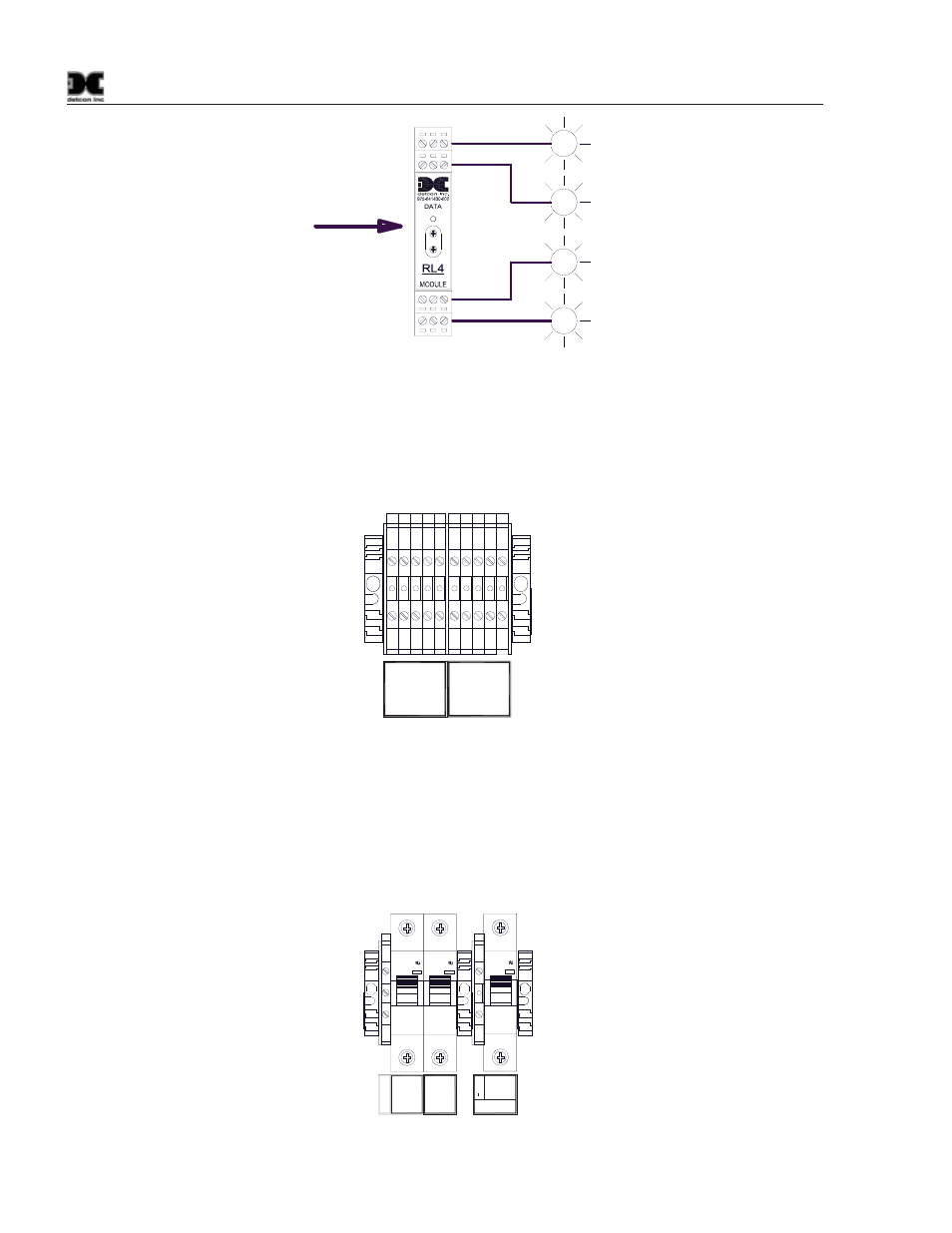
ALARM 1
ALARM 2
ALARM 3
FAULT
M
S
D
L
S
D
RS-485 from 880
Figure 12 Typical RL-4 Module
4. Terminal blocks are provided for connection to other external devices such as a remote display, a
printer, or other device capable of communication with the 880. The Remote display should be
connected to the “REMOTE OUTPUT” terminal blocks, and other devices should be connected to the
“RS-422 SLAVE” terminal blocks.
TXD+
TXD-
RXD+
REMOTE
OUTPUT
RXD-
0V
TXD+
TXD-
RXD+
RS-422
SLAVE
RXD-
0V
11 12 13 14 15 16 17 18 19 20
Part of
TB2
Figure 13 Main 880 terminal blocks and connections
5. If applicable, connect a 24VDC Battery Backup or Auxiliary 24V source to the Circuit Breaker
labeled “24VDC INPUT” (24V+ and 24V–) (Figure 14).
NOTE: This input should be capable of supplying at least 7 Amps at 24VDC in order for the unit to
operate properly. Insufficient current capabilities may cause detrimental damage to the unit and will
void the warranty.
I ON
C3
WMS1C03
240V-
10000
I ON
C3
WMS1C03
240V-
10000
Grou
nd
VAC (L1)
NEU (L2)
24V +
24V -
24VDC
INPUT
I ON
C03
WMS1C03
240V-
10000
Figure 14 Typical AC and DC Input Connections