Detcon 880S-N4X User Manual
Page 24
880-N4X
880-N4X Instruction Manual
Rev. 1.0
Page 20 of 40
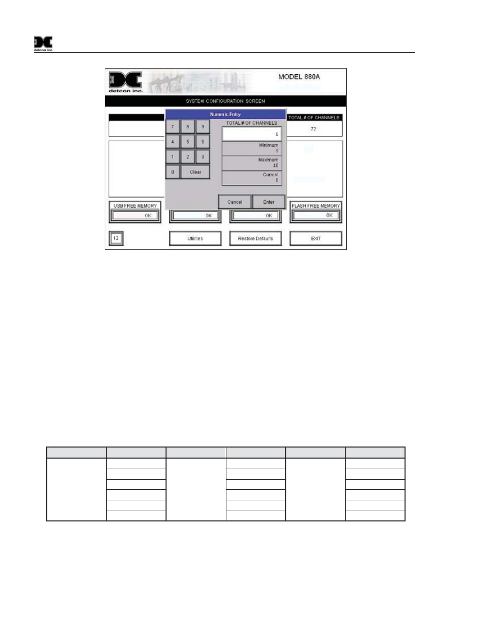
Figure 33 Inputting the number of channels
5) Select the “# OF RELAYS BANK 1”, “2”, and/or “3” Box and input the number of RL4 Modules that will
be attached to the unit for each “BANK” of alarms. (Maximum of 6 RL4 Modules per “BANK”). This
will configure the unit for those relay Modules.
NOTE: Pre-selected addresses are set in the firmware of the 880 for the alarm “Banks”. These addresses
are directly related to the RL4 module addresses and the RL4 relays used for annunciators. Each “Bank”
of alarms can have up to 6 related RL4 Modules associated with it, giving a maximum of 18 RL4
Modules that can be connected to the unit. Each RL4 Module must have its own discreet Modbus™
address, and that address must be enabled by the user before it can become operational.
a) To enable an RL4 module, the “Bank” must be chosen that the RL4 will be associated with, and the
number of RL4 Modules for that bank must be entered into the configuration of the 880.
b) Set the address on each RL4 module to the appropriate address for that “Bank”. Each RL4 Module
must have a distinct address, and the addresses for each bank must increase sequentially. The
addresses used by the 880 are listed in the following table.
Bank
RL4 Address
Bank
RL4 Address
Bank
RL4 Address
80h 86h 8Ch
81h 87h 8Dh
BANK
1 82h BANK
2 88h BANK
3 8Eh
83h 89h 8Fh
84h 8Ah 90h
85h 8Bh 91h
Each RL4 Module has one Relay for each alarm of that “Bank”. Alarm 1 is labeled on the RL4 Module as
Address 1, Alarm 2 is labeled as Address 2, Alarm 3 is labeled as Address 3, and Fault is labeled as Address 4
(refer to Figure 9).
6) Select the “EXIT” box to exit the “System Configuration Screen” and return to the “Main Screen”.