0 introduction, 1 analog systems (4-20ma sensors), 2 serial systems (rs-485) – Detcon 880S-N4X User Manual
Page 5
880-N4X
880-N4X Instruction Manual
Rev. 1.0
Page 1 of 40
1.0 Introduction
The standard Detcon Model 880 is a PLC based graphic control system specifically designed to serve as a host
monitoring and control system for networks of gas detection sensors as well as a wide range of other field
devices. The main unit is programmed as a Modbus master and is available in two versions: Serial (Model
880S-N4X) and Analog (Model 880A-N4X). Both are fully Field configurable and include a NEMA 4X rated
control enclosure, which is rain tight and suitable for outdoor locations in electrically non-hazardous
environments.
The Serial unit (Model 880S-N4X) is designed to monitor up to 32 serial field devices, while the Analog
version (880A-N4X) can monitor up to 72 analog devices via Detcon’s DA4 Modules. The unit features a
color touch screen that graphically displays the status of each device, provides three fully programmable
“Banks” of alarm outputs, and logs alarm events to a USB Drive (optional). The use of standard industrial
components makes Detcon Model 880 an easy and practical choice when configuring point-to-point
monitoring and data acquisition. The system can also be used for remote monitoring simply by adding the 880
Remote Display Unit.
1.1 Analog Systems (4-20mA sensors)
The signal outputs from multiple sensors provide the user with various options for integrating the Model 880
Graphic Control System. One method of integration is accomplished by using 4-20mA signal output gas
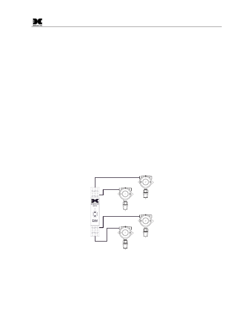
sensors with Detcon DA4 Modules (Figure 1). The DA4 Module receives an analog 4-20mA signal
corresponding to the range of detection then changes it to Modbus™ before relaying the information to the
880A. The Sensor’s output signal is calibrated so that a 4mA input represents a reading of “0” and a 20mA
input represents a reading of full scale. The scale used for each sensor is user programmable and can be set in
the field. Readings outside the range of 4-20mA will cause a Fault.
4-20mA
INPUT
COMM
M
S
D
L
S
D
Typical Sensors
Sensor 2
Sensor 1
Sensor 3
Sensor 4
Figure 1 DA4 4-20mA Configuration
Analog 4-20mA networks are typically recognized as the most fail-safe approach. When using DA4
Module(s), the 880A can communicate with up to 72 analog input channels.
1.2 Serial Systems (RS-485)
Another method of integration commonly used in industrial applications is the RS-485 serial communications