2 unit connections, I/o module addressing, Analog connections – Detcon 880S-N4X User Manual
Page 12: Figure 8 installing din-rail mounted modules, Figure 9 setting device addresses
880-N4X
880-N4X Instruction Manual
Rev. 1.0
Page 8 of 40
4-20mA
INPUT
COMM
M
S
D
L
S
D
RELAY
COMM
M
S
D
L
S
D
RELAY
COMM
M
S
D
L
S
D
RELAY
COMM
M
S
D
L
S
D
SBA
-
+
S
B
A
-
+
4-20mA
INPUT
COMM
M
S
D
L
S
D
RS-485 and Power Cable
RS-485
Cable to
Output Terminal
Blocks.
Add
Additional
Modules
as
needed.
Maximum
of 12
Modules.
TB3-J1
TB3-J2
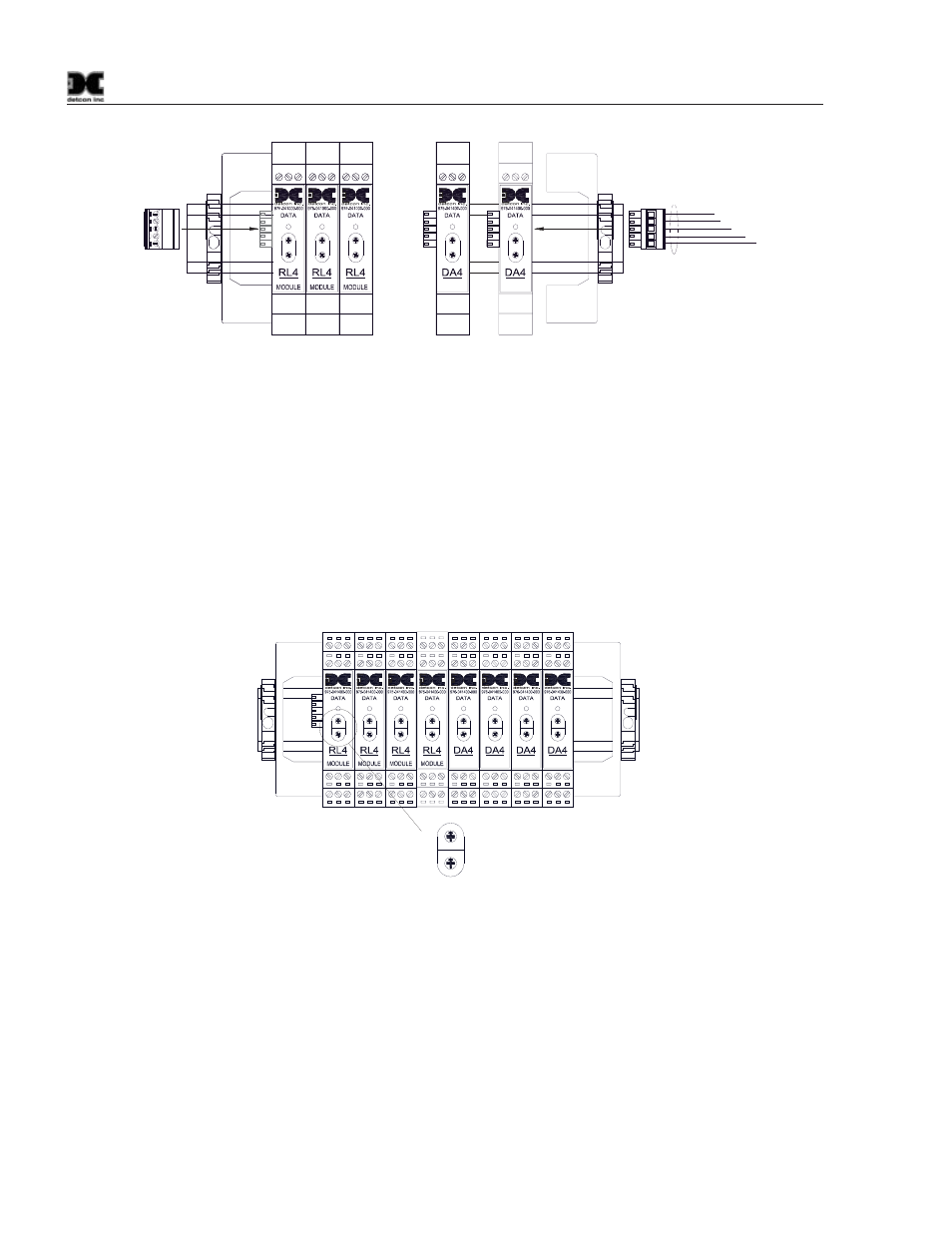
Figure 8 installing Din-Rail mounted modules
I/O Module Addressing
I/O modules must be properly addressed to establish correct communications. All Modules are addressed in
Hexadecimal. I/O Addressing is dependent on the type of module being installed, and is discussed in Section
4.3, 880 Setup. The I/O module’s address is established by setting the two rotary switches to the
correspondingly correct position. The top rotary switch sets the Most Significant Bit (MSB). The bottom
rotary switch sets the Least Significant Bit (LSB). For an address of 01, set the top switch (MSB) to 0 and the
bottom switch (LSB) to 1. See Appendix B for Decimal to Hexadecimal conversion.
NOTE: All addresses must be unique. There can be no duplication of addresses or a Communication
Error (NO COMM) will occur.
RELAY
COMM
M
S
D
L
S
D
4-20mA
INPUT
COMM
M
S
D
L
S
D
4-20mA
INPUT
COMM
M
S
D
L
S
D
4-20mA
INPUT
COMM
M
S
D
L
S
D
4-20mA
INPUT
COMM
M
S
D
L
S
D
RELAY
COMM
M
S
D
L
S
D
RELAY
COMM
M
S
D
L
S
D
RELAY
COMM
M
S
D
L
S
D
M
S
B
L
S
B
012
3
4
5
678
9A
B
C
D
EF
012
3
4
5
678
9A
B
C
D
EF
Figure 9 Setting Device Addresses
3.2 Unit Connections
Analog Connections
1. For Analog Units (880A), communication is accomplished by using Detcon DA4 modules and the RS-
485 Modbus™. The 4-20mA sensors are directly connected to the DA4 modules, while the DA4
modules are connected via the RS-485 Modbus™ to the 880 PLC (Figure 10). The correct setup of
the DA4’s is covered in Section 4.3 880 Setup.