3 initial power checks – Detcon 880S-N4X User Manual
Page 15
880-N4X
880-N4X Instruction Manual
Rev. 1.0
Page 11 of 40
6. Connect 110-220VAC input to the Circuit Breakers labeled “VAC (L1)” and labeled “NEU (L2)”.
Connect external ground to the Green/Yellow terminal labeled “GROUND” (Figure 14). The power
supply is able to accept AC input voltages from 100 to 240VAC at 50 or 60Hz.
General Wiring Notes:
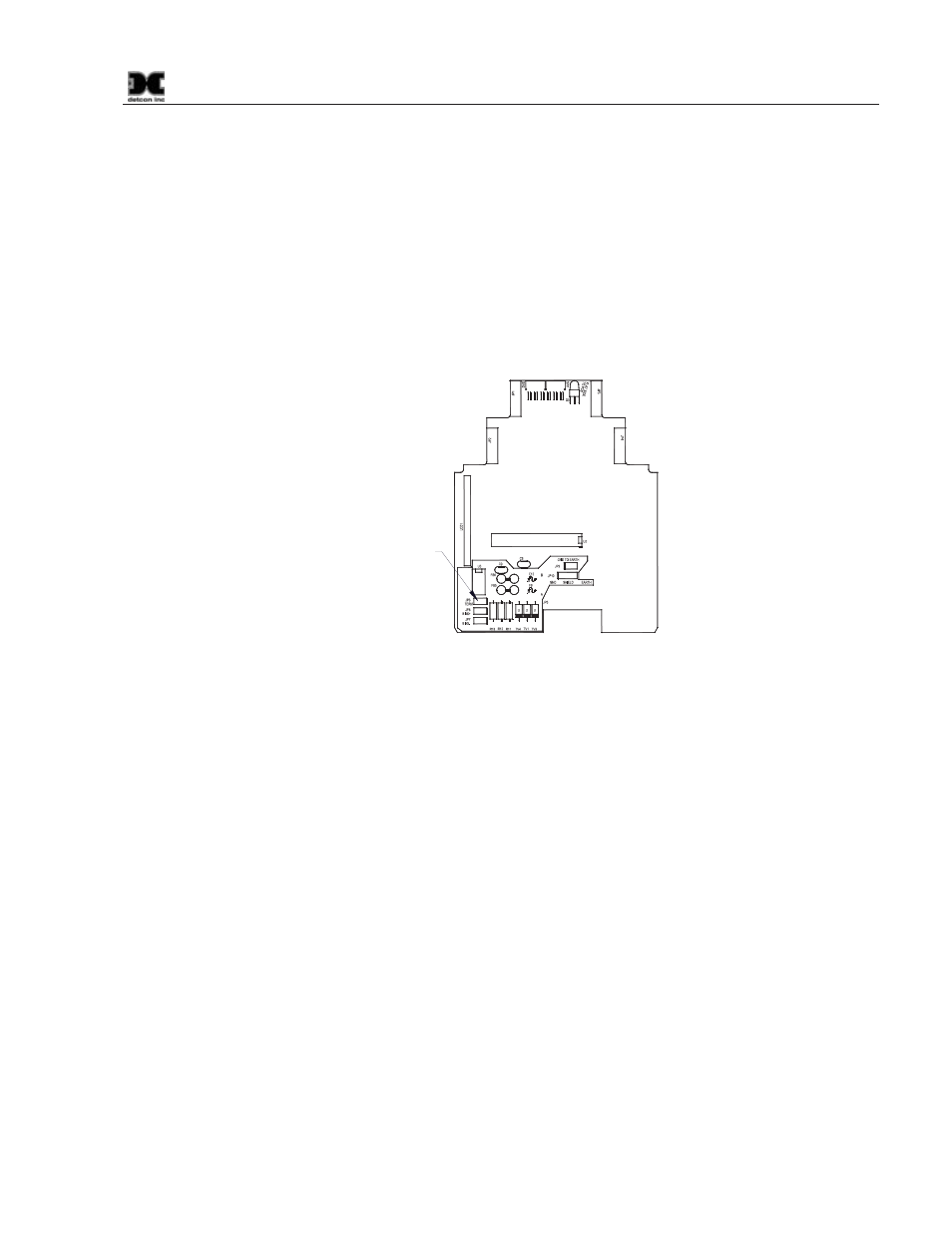
When I/O Modules are located at a remote distance from the controller, an end-of-line terminating resistor
is required to enhance communications reliability. Identify the last I/O Module in the loop, and open the
module casing using the clip release points. Locate and install the jumper on JP6 (TERM) Figure 15. This
adds a 120
: resistor to the end of the line. If applicable, add a 120: resistor to the last Modbus™ gas
sensor.
Jumper located
on component
side of PCB
Figure 15 I/O Module Termination jumper (JP6)
Follow generally accepted guidelines for RS-485 serial networks. Do not wire I/O Modules and/or
Modbus™ gas sensors in long-distance ‘T-Tap’ configurations. Stay with direct serial configurations. See
Appendix A for serial communications configuration guidelines.
Use Detcon Recommended cabling whenever possible.
x Belden P/N 1502P cable is recommended for a single cable providing serial communications and
power.
x Belden 9841 cable is recommended for a single cable providing serial communications only.
Ground the cable shielding at the Model 880 Controller only. Other points of grounding may cause a
ground loop, and induce unwanted noise on the RS-485 line, which in turn may disrupt communications.
3.3 Initial Power Checks
Upon completion of all field wiring, apply power to the 880 by: 1) setting both the AC Circuit Breakers and
DC Circuit Breakers to “ON”, 2) pushing the “POWER ON/OFF” switch on the front panel. The “POWER”
LED should illuminate. If all connections have been made properly, the “FAULT” and “ALARM” LED’s
should not be illuminated. The unit will go through a brief initialization and display the “Main Screen”
(Figure 29, Section 4.3). The “AC” box on the display should be green showing that AC is attached to the
unit. The “USB” box should be gray to indicate that no USB drive is attached.
Measure the voltage across the power supply output (V+ and V-). The reading should be 24 ±2.4VDC. If the
voltage is out of tolerance, make adjustments using the 24VDC Adjustment Potentiometer on the 24Volt
Power Supply.