0 installation, 1 installing i/o modules – Detcon 880S-N4X User Manual
Page 11
880-N4X
880-N4X Instruction Manual
Rev. 1.0
Page 7 of 40
3.0 Installation
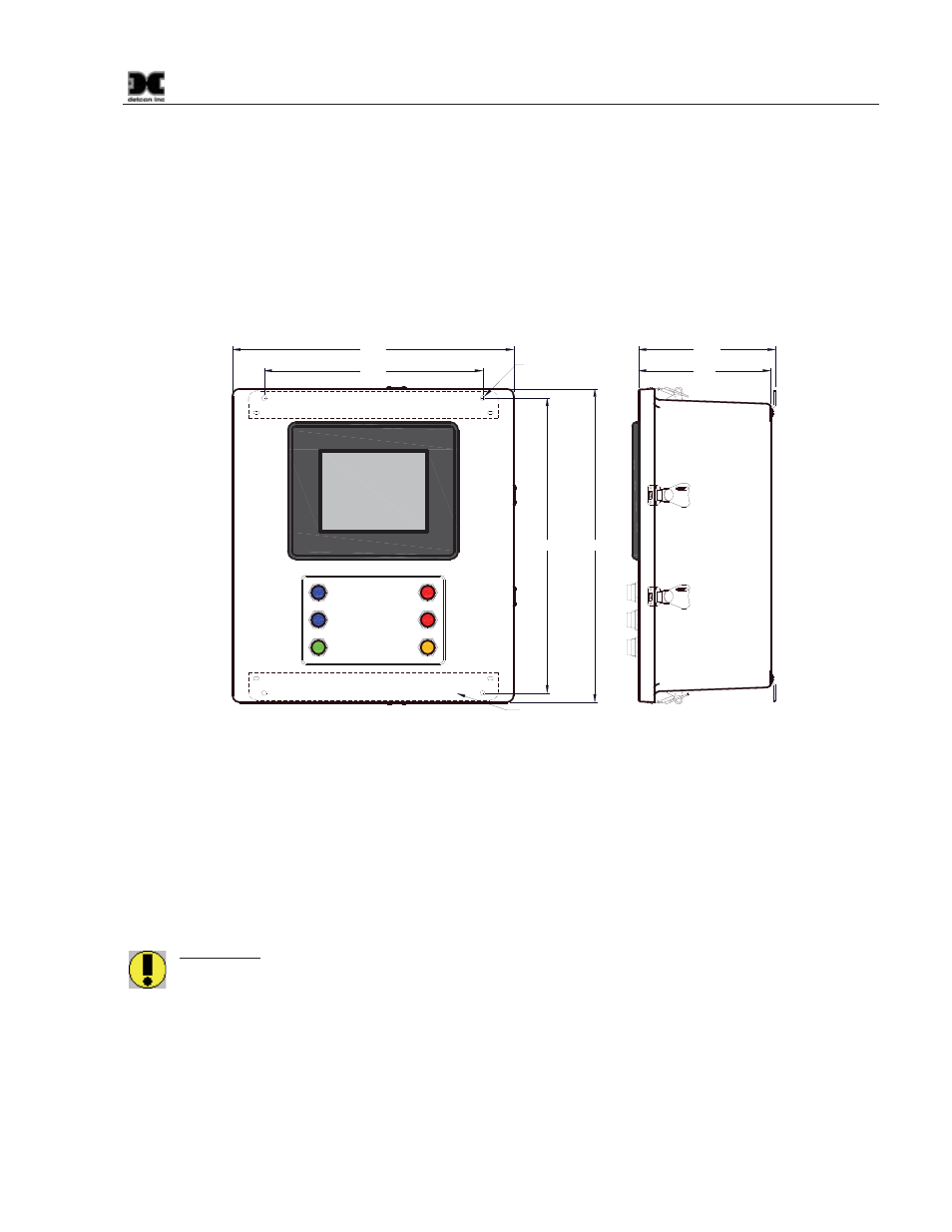
The Detcon Model 880 PLC is a wall-mount enclosure, and can be mounted anywhere that is rated safe for
NEMA 4X enclosures. The enclosure is equipped with wall-mounting flanges for easy wall mount
installations. Care should be given to prevent sharp objects from colliding with the touch screen display as
damage to the display may cause the unit to become inoperative. The screen can be cleaned with a mild
detergent and a lint free cloth. Never use an abrasive cleaner on the display.
Securely mount the 880 Enclosure in accordance with Figure 7.
ON / OFF
NO COMM
POWER
ALARM 1
ALARM 3
ALARM 2
FAULT
18.8"
20.0"
14.0"
18.0"
8.5"
8.75"
Ø0.3"
Mounting Flange
Figure 7 Dimensional Overview
3.1 Installing I/O Modules
The 880-N4X provides Din-Rail space for the addition of Din-Rail mounted I/O Modules. There is enough
room for the addition of up to 14 modules, but the number of modules that can be mounted should be
determined more by the current load imposed on the unit than by the physical space provided. The maximum
current load on internally mounted modules is to be restricted to 4Amps (96Watts). An RS-485 connector is
provided for Modbus™ and power connections for these Din-Rail mounted modules.
WARNING: The use of the 880’s 24VDC to power unit mounted Din-Rail modules and external
devices is be restricted to no more than 4Amps (96 Watts). Care should be taken to insure that the
total current of devices utilizing this power does not exceed this rating, as this may cause detrimental
damage to the unit and will void the warranty. An External Power Source should be used to power
any and all components or devices that exceed this rating.
I/O Modules should be mounted on the Din-Rail starting from the right and plugging additional modules in to
the left. An RS-485 cable with the appropriate I/O connector is provided on the right side of the Din-Rail and
should be plugged into the first module. An RS-485 connector is also provided to plug into the installed
modules on the left side. Both of the connectors must be plugged into the modules for RS-485
Communications to work properly.