Figure 14 fp-700 software flowchart – Detcon FP-700 User Manual
Page 18
Model FP-700
FP-700 Instruction Manual
Rev. 3.0
Page 14 of 40
Sensor Bridge Voltage
Gas Factor
Cal Factor
4-20mA Output
Input Voltage Supply
Operating Temperature
Set AutoSpan Level
Set Gas Factor
Set Cal Factor
Set Serial ID
Set Bridge Voltage
Signal Output Check
Restore Default Settings
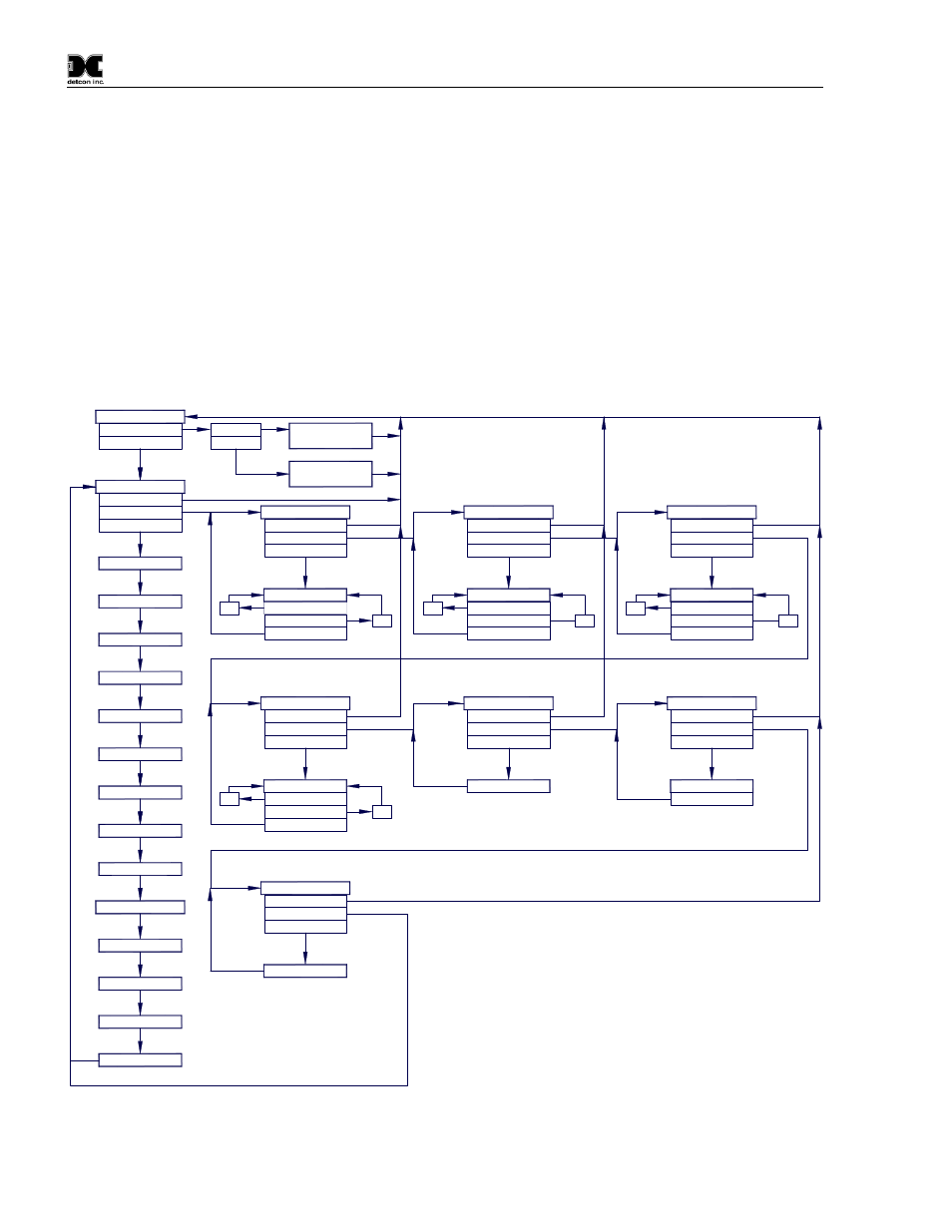
Software Flowchart
dec
Temp = XX C
mA Output = X.XX
Cal Factor = X.XX
Voltage = X.XX V
Sensor Life XXX%
Gas Factor = X.XX
Bridge A = XXX mA
Bridge V = X.XX VDC
PGM2 (10)
Defaults Restored
Restore Defaults
Auto Time-Out
PGM1/2 (M)
Setting Bridge
Calibration Mode
(Auto Span)
AutoSpan @ XX
Last Cal XX Days
Serial ID XX
Range XXX
Auto Time-Out
Version X.XX
View Sensor Status
Model Type
PGM1/2 (3)
PGM1/2 (M)
inc
PGM1 (S)
Set Serial ID
PGM1/2 (3)
PGM1/2 (M)
PGM1/2 (3)
Auto Time-Out
AutoTime-out
XX
PGM2 (S)
PGM1/2 (3)
PGM1/2 (M)
Set AutoSpan Level
PGM1 (3)
PGM2 (3)
Normal Operation
PGM1 (3)
PGM2 (10)
Calibration Mode
(Auto Zero)
inc - Increase
dec - Decrease
X, XX, XXX - numeric values
(S) - Momentary Swipe
(M) - Momentary hold of Magnet during teXt
scroll until the ">" appears, then release
(3) - 3 second hold from ">" prompt
(10) - 10 second hold from ">" prompt
Auto Time-out - 5 seconds
PGM1 - Program Switch Location X1
PGM2 - Program Switch Location X2
LEGEND:
inc
PGM2 (S)
PGM1/2 (3)
PGM1 (S)
XX
dec
PGM1/2 (3)
Simulation
Auto Time-Out
Set Cal Factor
Auto Time-Out
Signal Output Check
Auto Time-Out
Set Bridge Voltage
Auto Time-Out
Set Gas Factor
PGM1 (S)
PGM1/2 (3)
PGM1/2 (M)
PGM1/2 (3)
inc
PGM1/2 (3)
PGM2 (S)
XX
PGM1/2 (M)
dec
inc
dec
PGM1 (S)
PGM2 (10)
PGM1/2 (M)
PGM1/2 (3)
PGM1/2 (3)
PGM2 (S)
XX
PGM1/2 (M)
Figure 14 FP-700 Software Flowchart