Analog output 4-20 ma, Relay contact ratings, Dimensions – AW Gear Meters FEM-03 User Manual
Page 10: Input and output wiring connections, Fem-03 flow monitor
FEM-03 Flow Monitor
Operation and Programming Manual
9
Analog Output 4-20 mA
self-powered loop output into a maximum 400 Ohm load impedance
Relay Contact Ratings
Maximum
Switched
Power
Resistive Load
DC: 60W
AC: 125VA
Inductive Load
DC: 30W
AC: 60VA
Maximum Switched Voltage
220V DC, 250V AC
Maximum Switched Current
2A
Rated
Load
Resistive Load
DC: 30V, 2A
AC: 110V, 0.5A
Inductive Load
DC: 30V, 1A
AC: 110V, 0.3A
Do not use 115 VAC through relay contacts. Use 24 VDC instead.
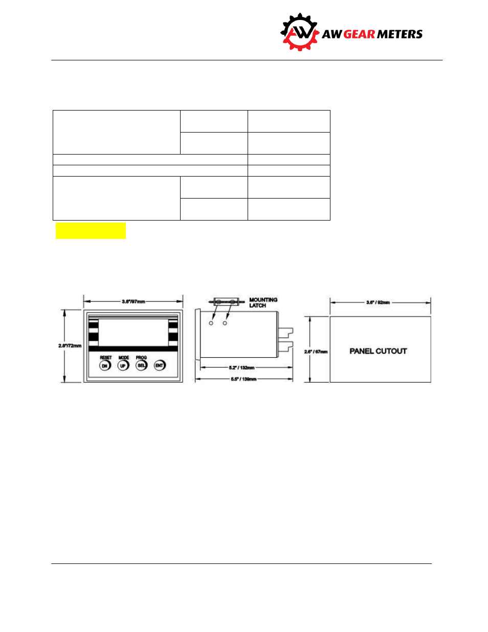
Dimensions
Input and Output Wiring Connections
Make all connections to the FEM-03 from the back of the unit. A plug-in connector from the wall plug-
type power supply, normally supplied with the unit, delivers power. If necessary, any standard AC wall
plug unit providing 13-17VAC/250mA. or 18-24VDC/250mA. may be used. A standard female plug
(2.1mm I.D. x 5.5mm O.D.) supplies AC or DC power to the FEM-03. This connector is polarity insensitive.
The factory recommends tying one of the DC COMMON terminals to earth ground, especially for DC
operation.
Make all other connections through the two rear terminal connectors. Called the “upper” and “lower”
connectors, they are removable and have ten connections each. A label on each connector shows
connection information. Refer to the Connection Diagram on page 12 for details and typical
Caution