Caution – Star Water Systems SJ05SAT20H User Manual
Page 3
© 2014 Star Water Systems. All rights reserved. 4
© 2014 Star Water Systems. All rights reserved. 5
IL1104
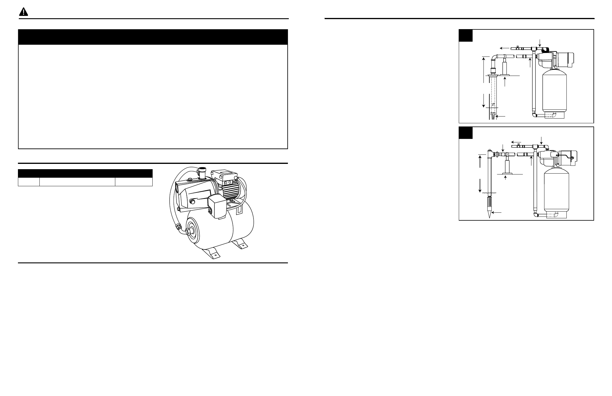
Water Level
25 ft.
Max
Suction
Lift
3/4 or 1 in.
Discharge Pipe
1-1/4 in.
Suction
Pipe
Discharge
to Home
Pipe
Support
Foot Valve
Ventilation - Ventilation and drainage must be provided to prevent damage to the motor from heat
and moisture.
Freezing - Pump/tank and all piping must be protected from freezing. If freezing weather is forecast,
drain pump or remove completely from the system.
Water Supply - The water source must be able to supply enough water to satisfy the capacity of
pump/tank and water needs. See performance chart on page 2.
Suction Lift - Suction lift is the vertical distance from the lowest level of the water to the pump/tank
intake. Pump/tank will move water as long as it is within 25 vertical ft. of the water source.
Horizontal Distance - The horizontal distance is the horizontal measurement between pump/tank
suction and the water source. This distance may affect the ability of pump/tank to operate. If it is more
than 100 ft., call the manufacturer for assistance: 1-800-742-5044.
PACKAGE CONTENTS
IL1472
Water Level
25 ft.
Max
Suction
Lift
3/4 or 1 in.
Discharge Pipe
1-1/4 in.
Suction
Pipe
Discharge
to Home
Pipe
Support
Drive Point
Check
Valve
SAFETY INFORMATION
CAUTION
PRODUCT DAMAGE MAY RESULT
This pump is not to be used for irrigation or water systems.
PRODUCT DAMAGE MAY RESULT
Protect the power cable from coming in contact with sharp objects.
PRODUCT DAMAGE MAY RESULT
Do not run pump dry.
PRODUCT DAMAGE MAY RESULT
Pump and plumbing must be full of water before startup.
PRODUCT DAMAGE MAY RESULT
Do not pump water which contains sand, mud, silt, or debris.
INJURY MAY RESULT
Be careful when touching the exterior of an operating motor. It may be hot enough to be painful or
cause injury.
1
2
GENERAL PUMP INFORMATION
Typical Pump Setup
1. Shallow well jet pumps are designed for use
where the suction lift is 25 ft. or less. They
can be used with drilled or cased wells.
2. Jet pumps can also be used with dug wells,
driven wells or with cisterns or lakes.
PART
DESCRIPTION
QUANTITY
1
Pump/Tank
1
PREPARATION
Before beginning installation of product, make sure all parts are present. If any part is missing or
damaged, do not attempt to assemble the product. Compare parts to package contents list and
hardware contents list.
Estimated Installation Time: 2 hours.
Tools Required for New Installation (not included): pipe wrench, pliers, Phillips screwdriver, pipe clamp,
2-step PVC glue system (primer and sealer), thread tape, tire gauge
Parts Required for New Installation (not included):
well seal, 1-1/4 in. male PVC adapter (2), 1 in. male
PVC adapter, 1-1/4 in. foot valve, 1-1/4 in. PVC pipe and couplings, 1 in. PVC pipe and couplings, 1-1/4
in. PVC elbow, 1 in. discharge tee, galvanized bushing, pressure gauge (optional) or pipe plug, 1-1/4 in.
union (optional), 1 in. union (optional), electrical wire, electrical wire strain relief, shut off valve (optional)