Hired-Hand PowerTrak: Load Block - Drive Screw Replacement User Manual
Page 6
HIRED-HAND MFG., INC. • 1733 County Rd 68 • Bremen, Alabama 35033 · Phone 256-287-1000 • Fax 256-287-2000
Part No. 4802-5093 rev 5-07
Page 6 of 8
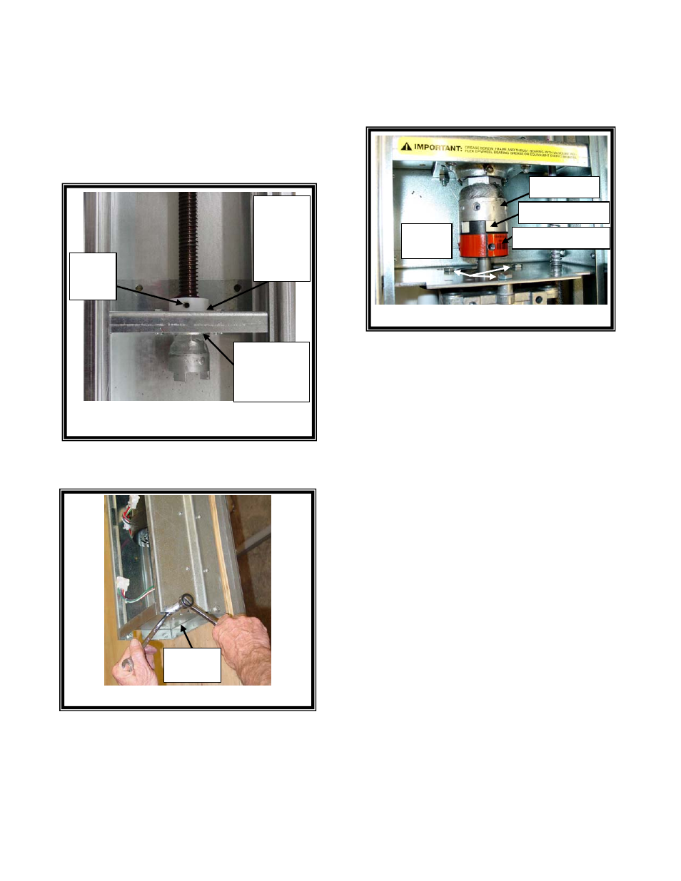
Figure 14 – Attach Bottom Plate
Bottom
Plate
Figure 13 – Delrin Bushing
Delrin
Set
Screw
Delrin
Bushing
flush
against
Bearing
Plate
Drive Screw
flush against
Thrust
Bearing
Motor
Screws
Figure 15 - Motor Screws
Drive Screw
Spider Coupling
Lovejoy Coupling
(6)
Rotate the delrin bushing downward by hand
until the drive screw is flush against the thrust
bearing on the bottom side and the delrin
bushing is flush against the bearing plate on the
top side. Do not overtighten the delrin bushing.
The delrin bushing must be able to freely turn
with the drive screw. Hand-tighten the set
screw. Refer to Figure 13.
DO NOT OVERTIGHTEN THE SET SCREW.
(7)
Attach the bottom plate with the four screws &
nuts. Refer to Figure 14.
(8)
Install the motor with the three/four motor
screws. Ensure the drive screw, spider
coupling, and lovejoy motor coupling are
correctly installed as shown. Refer to Figures
1 & 15.
(9)
Connect the motor quick-disconnect connector.
(10)
Ensure the Limit Adjustment Collars are near
the marked positions, verify placement of the
Tensioning Springs, and install the three Cotter
pins in the Guide Rod. Refer to Figure 1.
(11)
Align the cam block and guide rod based upon
the markings from Step (5) and Figure 2 on
Page 2. Tighten the set screw on the Limit
Switch Assembly with a 3/32" allen wrench.
(12)
Set the upper and lower limit adjustment collar
positions based upon the markings from Step
(5) and Figure 2 on Page 2. Tighten the limit
adjustment collars using a 3/32" allen wrench.