Caution, Warning – Hired-Hand PowerTrak: Load Block - Drive Screw Replacement User Manual
Page 4
HIRED-HAND MFG., INC. • 1733 County Rd 68 • Bremen, Alabama 35033 · Phone 256-287-1000 • Fax 256-287-2000
Part No. 4802-5093 rev 5-07
Page 4 of 8
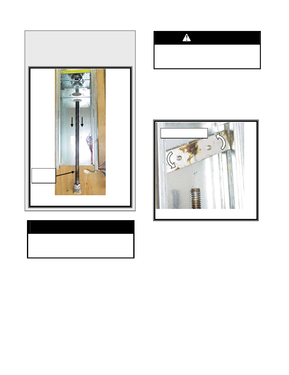
Figure 9 – Remove Old Load Block
Twist Load Block
Figure 8 – Drive Screw
Drive
Screw
NOTE: If the Drive Screw is not being replaced, skip
Steps 19 and 20 and continue at Step 21.
(19) Remove the delrin bushing from the drive screw.
(20) Remove the drive screw from the PowerTrak
™.
Refer to Figure 8.
CAUTION!
Ensure Extra Care Is Taken To Prevent Bending
The Guide Rod During This Process. If The Guide
Rod Is Bent, Excessive Rod Wear And/Or
Functional Problems May Occur.
(21) Slide the load block over the top of the drive
screw and the guide rod.
WARNING!
The PowerTrak Enclosure Contains Sharp Metal
Edges. Wear Gloves During This Next Step And
Ensure That Extra Care Is Taken To Prevent
Personnel Injury Or Equipment Damage.
(22) Twist the load block out of the side tracks. Refer
to Figure 9.
NOTE: Do Not Pry Or Use Tools To Remove The Load
Block Assembly From The Side Tracks. The
Side Tracks Can Be Damaged If Tools Are Used.
(23) Inspect the side tracks for denting or burrs which
may interfere with smooth Load Block operation.
IMPORTANT: Do Not Reuse The Aluminum Load
Block. Replacement Of The Complete
Load Block Assembly Is Required.