Caution, Warning – Hired-Hand PowerTrak: Load Block - Drive Screw Replacement User Manual
Page 2
HIRED-HAND MFG., INC. • 1733 County Rd 68 • Bremen, Alabama 35033 · Phone 256-287-1000 • Fax 256-287-2000
Part No. 4802-5093 rev 5-07
Page 2 of 8
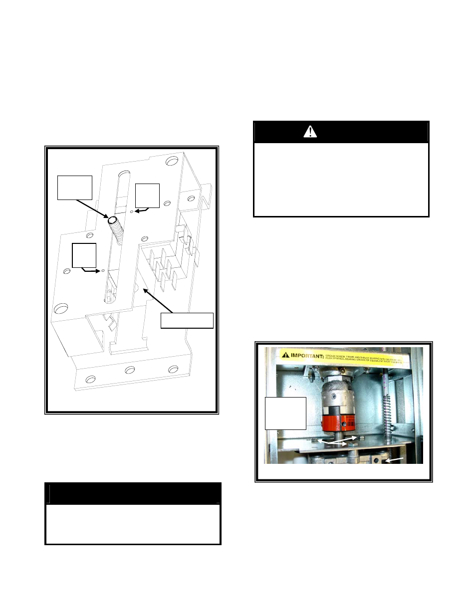
Remove
3-4 Motor
Screws
Motor
Figure 3 - Motor Screws
(5)
To minimize re-alignment of the limit switches,
use a permanent marker to mark the following
items position:
• High and low limit adjustment collars on the
guide rod. Refer to Figure 1.
• The guide rod entering the cam block in the
limit switch housing. Refer to Figure 2.
• The position of the limit switch set
screw/cam block relative to the limit switch
housing. Refer to Figure 2.
(6)
Loosen the high and lower limit adjustment
collars using a 3/32" allen wrench. Refer to
Figure 1.
(7)
Remove the three cotter pins or roll pins in the
Guide Rod above the tensioning springs. Refer
to Figure 1.
CAUTION!
Ensure Extra Care Is Taken To Prevent Bending
The Guide Rod During This Process. If The Guide
Rod Is Bent, Excessive Rod Wear And/Or
Functional Problems May Occur.
(8)
Loosen the set screw on the limit switch assembly
with a 3/32" allen wrench. Refer to Figure 2.
(9)
Drop the guide rod to the bottom of the enclosure.
NOTE: If the load block is already within 4 inches of the
top of the drive screw, skip Steps 10-12 and
continue at Step 13.
(10) Connect Electrical Power to the Power Trak
™.
WARNING!
• Only A Qualified Electrician Should Perform
Necessary Electrical Connections.
• Keep Hands And Clothing Away From
Rotating And Moving Parts.
FAILURE TO FOLLOW THESE
INSTRUCTIONS MAY RESULT IN PROPERTY
DAMAGE, SERIOUS INJURY, OR DEATH.
(11) Turn the motor on and run the Load Block to within
4 inches of the top of the Drive Screw. If the Load
Block is completely stripped, disconnect all
electrical power and run Load Block upward by
hand.
(12) Disconnect all Electrical Power from the Power
Trak
™.
(13) Unplug the motor quick-disconnect.
(14) While supporting the motor, remove the three/four
motor screws/nuts and set the motor aside. Refer
to Figure 3.
Figure 2 – Limit Switch
Figure 2 – Limit Switch Assembly
Mark
Here
Set
Screw
Mark
Here
Cam Block