Hired-Hand PowerTrak: Load Block - Drive Screw Replacement User Manual
Page 5
HIRED-HAND MFG., INC. • 1733 County Rd 68 • Bremen, Alabama 35033 · Phone 256-287-1000 • Fax 256-287-2000
Part No. 4802-5093 rev 5-07
Page 5 of 8
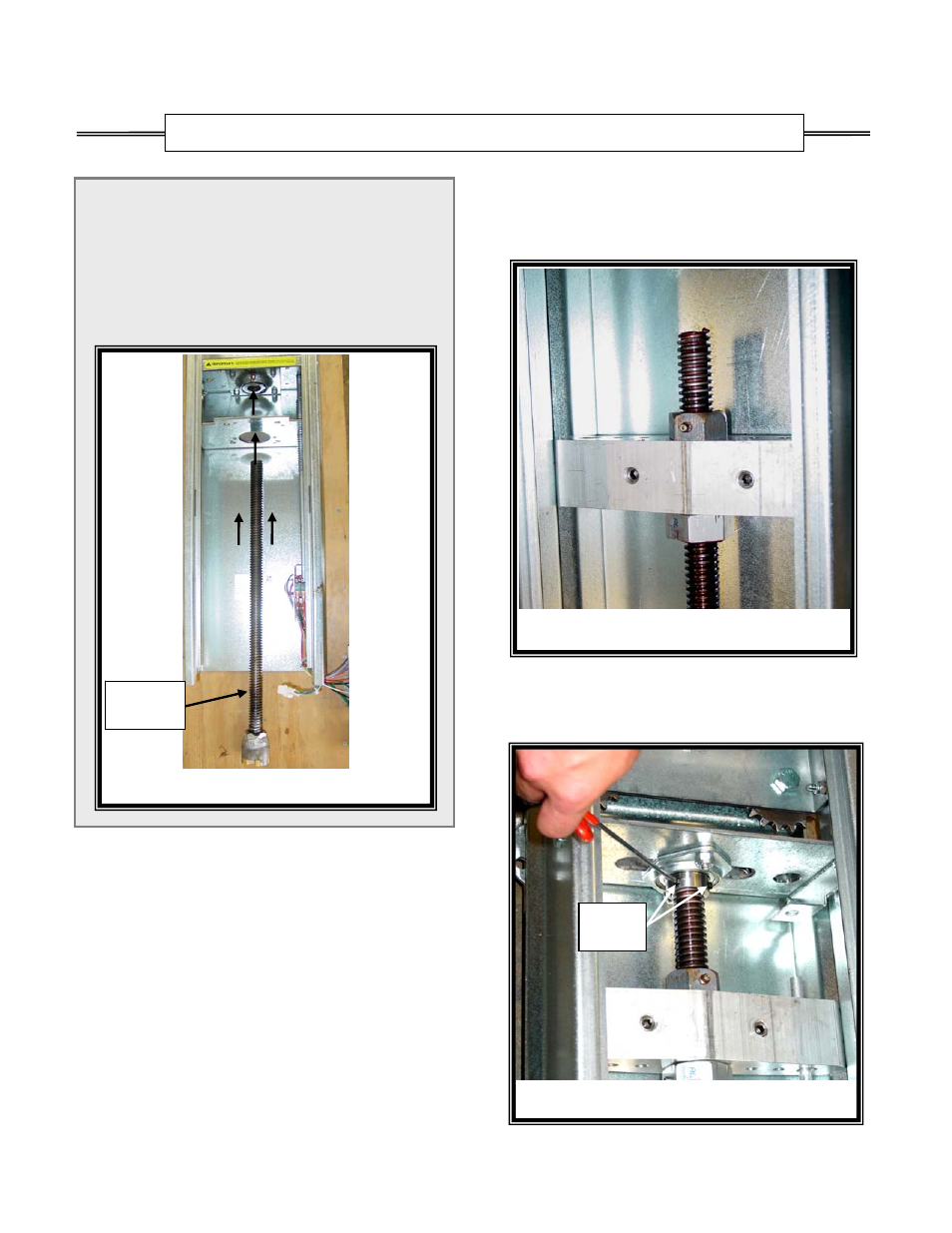
Figure 12 – Upper Radial Bearing
Set
Screws
Figure 10 – Drive Screw
Drive
Screw
NOTE: If the Drive Screw was not replaced, skip Steps
1 and 2 and continue at Step 3.
(1)
Insert the drive screw through the PowerTrak
™
thrust bearing. Refer to Figure 1 and 10.
(2)
Attach the delrin bushing to the drive screw.
Turn the drive screw by hand and run the delrin
bushing down the drive screw approximately 8
inches.
NOTE: Ensure the new load block assembly is placed in
the correct orientation: The grease fitting and
cable locking set screws must point outward.
The nut with the grease fitting should be on the
top side toward the pulley assembly.
(3)
Rotate the new load block into the side tracks
above the drive screw and the guide rod while
observing correct orientation.
(4)
Slide the load block over the top of the drive
screw and the guide rod. Turn the drive screw by
hand and run the load block down the drive screw
approximately 4 inches. Refer to Figure 11.
(5)
Push the drive screw upward into the upper radial
bearing and ensure the bottom of the drive screw
is flush against the thrust bearing. Tighten the
two set screws. Refer to Figures 12 & 13.
SECTION 2: New Load Block and/or Drive Screw Installation
Figure 11 – Install New Load Block