Hired-Hand PowerTrak: Load Block - Drive Screw Replacement User Manual
Installation instructions, Load block / drive screw replacement, Warning
INSTALLATION INSTRUCTIONS
LOAD BLOCK / Drive Screw REPLACEMENT
®
HIRED-HAND MFG., INC. • 1733 County Rd 68 • Bremen, Alabama 35033 · Phone 256-287-1000 • Fax 256-287-2000
Part No. 4802-5093 rev 5-07
Page 1 of 8
Optional Kits
Kit Part #’s
Description
6450-5049
Kit, PT Load Block Replacement
NOTE: For Load Block replacement
6450-5120
Kit, PT Load Block / Drive Screw Replacement
NOTE: For Load Block and Drive Screw replacement
Tools Required:
3/8" Ratchet and extensions
7/16" Socket
¼" Nut Driver
11/32" Allen wrench
Grease gun
Small screwdriver
9/16 " Socket
7/16 " Wrench
3/32" Allen wrench
WARNING!
These procedures require that the Electrical Power Sources be used during part of the installation.
Use CAUTION when working inside unit with the power ON.
DESCRIPTION
This instruction manual describes the disassembly and
reassembly of a PowerTrak
™ unit to replace a worn Load
Block and/or Drive Screw Assembly. The 6450-5049 kit
includes a new load block assembly and four cotter pins.
The 6450-5120 includes a new load block assembly, four
cotter pins, and a new Drive Screw. It is very important
to require replacement of the complete load block
assembly and not only portions of the assembly.
When the kit is received, check for shipping damage or
missing parts.
INSTALLATION
(1)
Disconnect all electrical power from the Power
Trak
™.
(2)
Open and remove the front access door.
WARNING!
Do Not Loosen The Curtain Cables From The Load
Block While Tension Remains On The Cables. The
Sudden Release Of The Cables Under Tension
Could Cause Personal Injury And/Or Property
Damage.
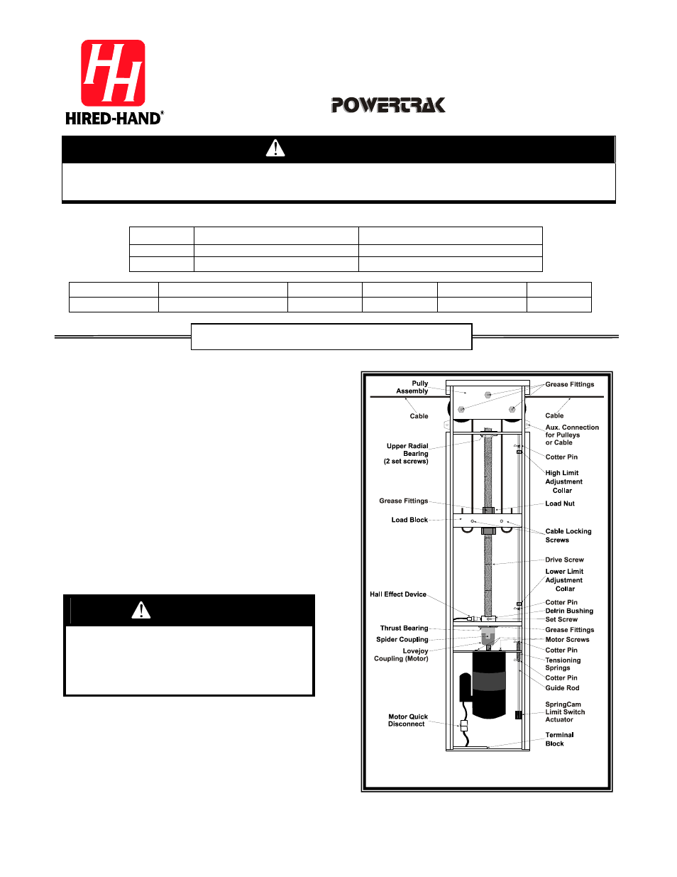
(3)
Remove tension from the PowerTrak
™ load block
cables, loosen the cable locking screws, and
disconnect the cables from the load block. Refer
to Figure 1.
(4)
Remove the cables completely from the Power
Trak
™ unit.
SECTION 1: Old Load Block Removal
Figure 1 – PowerTrak
™ Assembly