Apply power, Day to day operating instructions – Hired-Hand Emergency Back-Up and Alarms: Farm Hand Back Up System User Manual
Page 6
4801-5048
Farm Hand 4-ST
&
8-ST
5
SWX4-One /Two Sensor Option
For one room operation, this switch selects either one or two sensors. If the
switch is in the ON position then the average temperature of Sensor 1 and
Sensor 2 is used as reference and displayed as Room Temp. If the switch is in
the OFF position then Sensor 1 is selected as the reference and displayed as
the Room Temp. For two room operation and with this switch either ON or
OFF, sensor 1 is used as a reference for stages 1 and 2 and sensor 2 is used as
a reference for stages 3 and 4. Sensor 1 and sensor 2 readings are alternately
displayed as Room Temp.
SWX5-115/230v Switch
This switch selects the line voltage. The voltage positions are labeled on the
switch. IMPORTANT: THIS SWITCH MUST BE SET TO THE
CORRECT POSITION BEFORE PLUGGING THE UNIT INTO
POWER SOURCE.
4. Apply Power
Connect the electrical wires to the controller as shown. (Note: Refer to Wiring Diagrams in the
back of this manual). After setting the SWX5 switch to the correct voltage, turn on the electrical
power.
5.
Day to Day Operating Instructions
The Farm Hand Back Up System supplements a primary temperature controller such as a Farm Hand
ST by providing auxiliary heat/cool stages and optional one room or two room temperature sensors.
The Farm Hand Back Up can be set so that the High and Low Limits provide “back up” for a
primary controller in the event of extreme variations from the target temperature or if the primary
controller malfunctions.
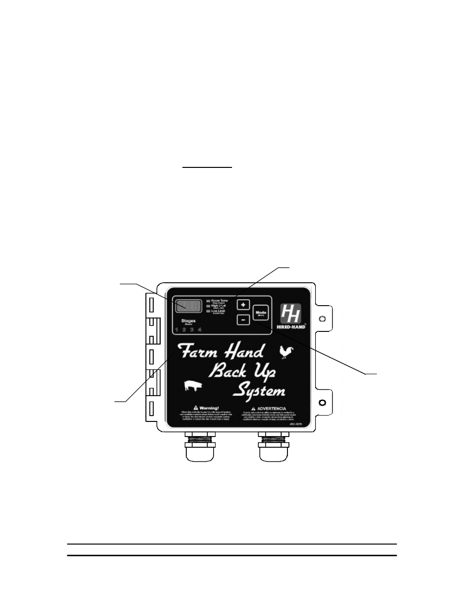
Control Buttons
Mode, +, and -
Main Display
Stage Indicators
Display Indicators