Warning – Hired-Hand Emergency Back-Up and Alarms: Farm Hand Back Up System User Manual
Page 11
4801-5048
Farm Hand ST
10
9.
Wiring Diagrams
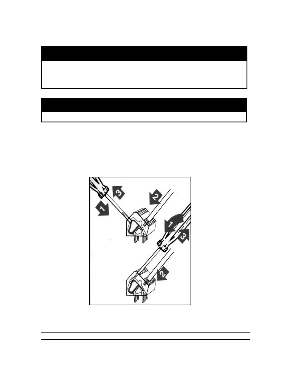
All wiring connections for stages, inside the controller are made without terminals on the end of
the wire. To make the connection, strip about ¼” of the insulation off the wire, and follow the
diagram below.
1. Insert a small screwdriver into either the hole shown in the diagram.
2. Insert the stripped end of the wire into the hole shown in the diagram.
3. Remove the screwdriver, and tug slightly on the wire to check that it is snug.
Before connecting power to the machine, be sure to check the position of the
voltage selector switch located next to the transformer on the relay board.
Improper positioning of this switch will cause system failure.
Warning!
Do not connect more than twelve (12) amps of load to any one stage.
Warning!