Step 2, Step 5, Status led – Hired-Hand HH Software: 900SS Wireless Network User Manual
Page 6: 12v gnd shield local network
Part No. 4801-2995
900SS Wireless Network 4
6.2 Installing Control Side of Wireless HH.Net
Step 1. It is recommended to use the Wireless Tuning
Software with a PDA to ensure that you have the best signal at
a particular mounting point. See Section 7.
Step 2.
Mount the 900SS Module where it has the best line of
site to the 900SS module on the computer side. Use
appropriate mounting hardware for wood, masonry or other
material.
Step 3. Run twisted pair wire from 900SS Module to the first
control. If the Evolution control is on the network, connect to
it first. The power supply and HH.Net wires can be in the same
jacket.
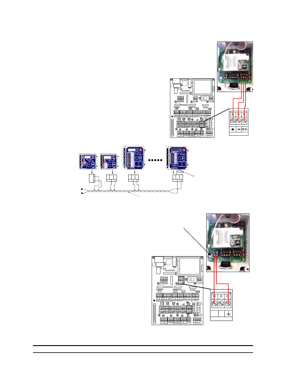
Step 4. Wire the HH.Net connection from the 900SS Module
to the control as shown to the right.
Step 5.
Connect the other controls in parallel as shown below.
Step 6. Wire Power supply connection to 900SS.
Power supply and HH.Net cables can be run in the
same jacket.
A. If connecting to a Farm Hand Alarm or an
Evolution Controller, the power supply can be
connected directly to the control. See diagram at
right.
B. If you are not connecting to an Evolution or
Farm Hand Alarm or the 900SS is further than 30
feet, use an external power supply, HHI Part
Number 1902-2993. See diagram shown in
Section 6.1.
C. After all connection are made, if Farm Manager
is running on PC side, check the LED on the
900SS Radio. If the controller is
communicating, you should see the Status LED
flash orange. See Section 8.1 for further details.
900SS to Control
Network Connection.
Close
Aux.
+12V
+12V
Com.
Auxilliary Inputs
Relay Control
Tunnel Aux. Input Vent Aux. Input
Relay Control
Variable Module
HHNet Termination
Power Ventilation Module
Natural Ventilation Module
Var #1
Var #2
Open
U1
Open
U1
Open
U2
Open
U2
Open
AUX
Close
AUX
Open
AUX Com
Close
AUX
Com
Com.
Close
Aux.
Close
U1
Close
U1
Close
U2
Close
U2
+
+
-
-
+12V
GND Shield
Local Network
-
Sensor #1
Te
m
per
at
ur
e
S
en
so
rs
Te
m
per
at
ur
e S
en
sor
s
Black
Black
Black
Black
Black
Black
Black
Black
Black
White
Shield
White
Shield
White
Shield
White
Shield
White
Shield
White
Shield
White
Shield
White
Shield
White
Shield
Sensor #2 Sensor #3 Sensor #4 Sensor #5 Sensor #6 Sensor #7 Sensor #8
Outside
N.C.
IN
N.C.
OUT
N.O.
IN
N.O.
OUT
Auxilliary Alarm
DC Power Supply
+12V +5V
115 V
230 V
AC Supply
L1
L2
Evolution Control
900SS
The Diagram shown is for the Evolution Control all of the PC
compatible Farm Hands will connect the same way.
DAT
A
+
-
GN
D
HI
LO
HH NET
GN
D
HI
LO
HH NET
GN
D
HI
LO
HH NET
+
-
Terminating
Resistor
*Note: A 120 ohm terminating resistor must
be placed across the network, as shown on
the last controller on the network wire.
*Note: Twisted pair wire
can extend up to 4000 ft.
Close
Aux.
+12V
+12V
Com.
Auxilliary Inputs
Relay Control
Tunnel Aux. Input Vent Aux. Input
Relay Control
Variable Module
HHNet Termination
Power Ventilation Module
Natural Ventilation Module
Var #1
Var #2
Open
U1
Open
U1
Open
U2
Open
U2
Open
AUX
Close
AUX
Open
AUX Com
Close
AUX
Com
Com.
Close
Aux.
Close
U1
Close
U1
Close
U2
Close
U2
+
+
-
-
+12V
GND Shield
Local Network
-
Sensor #1
Te
m
per
at
ur
e
S
ens
or
s
Te
m
per
atur
e Se
nso
rs
Black
Black
Black
Black
Black
Black
Black
Black
Black
White
Shield
White
Shield
White
Shield
White
Shield
White
Shield
White
Shield
White
Shield
White
Shield
White
Shield
Sensor #2 Sensor #3 Sensor #4 Sensor #5 Sensor #6 Sensor #7 Sensor #8
O utside
N.C.
IN
N.C.
OUT
N.O.
IN
N.O.
OUT
Auxilliary Alarm
DC Power Supply
+12V +5V
11
5 V
23
0 V
AC Supply
L1
L2
Evolution Control
900SS
+12V
+5V
DC Power Supply
Status LED