General, Framing diagram – Hired-Hand Tunnel Doors User Manual
Page 4
Part No. 4801-3500 Rev 2/08
Installing Tunnel Door
Page 4 of 16
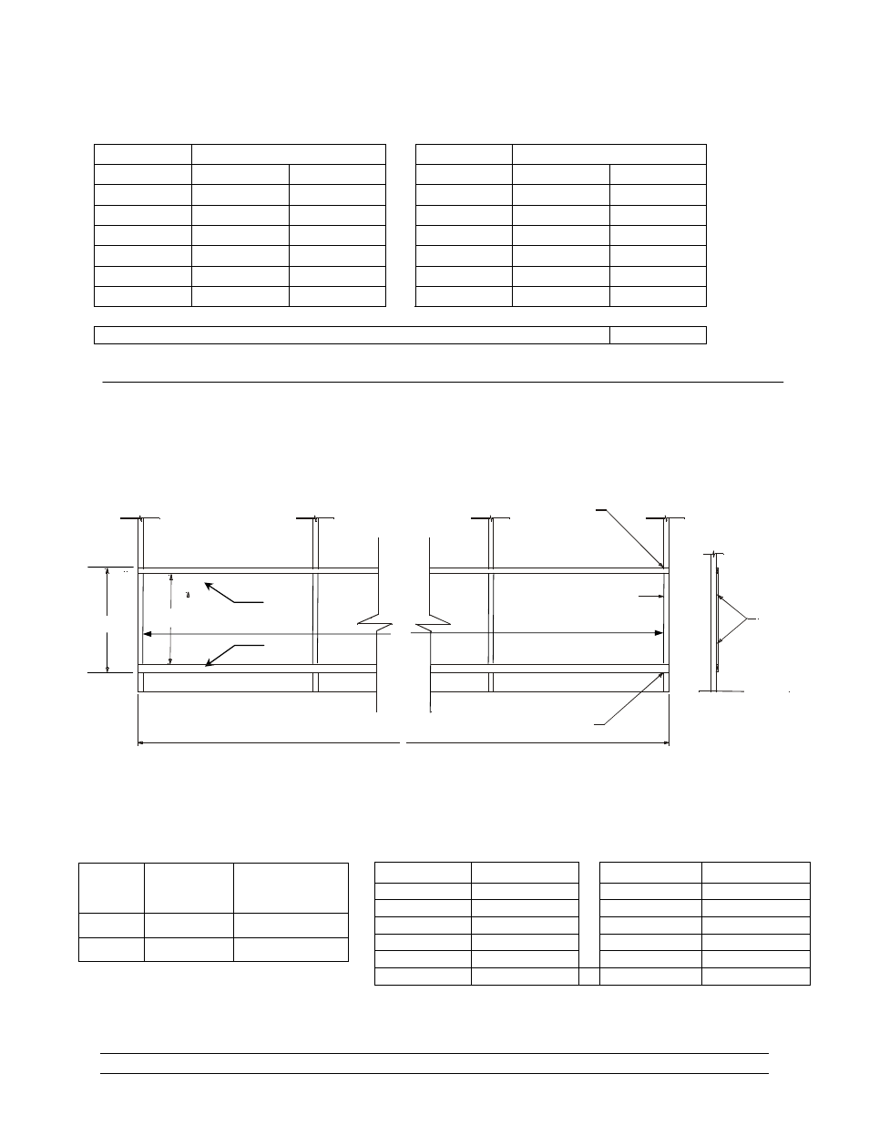
Figure 1 – Tunnel Door Framing Diagram
NOTE: X is determined by length of tunnel inlet of existing house. The opening is to be 2”
less on each end than the tunnel door length.
2. General
Part Numbers
System
System
Length
5 Foot
4 Foot
Length
5 Foot
4 Foot
10 ft
6609-4540 6609-4552
70 ft
6609-4546 6609-4558
20 ft
6609-4541 6609-4553
80 ft
6609-4547 6609-4559
30 ft
6609-4542 6609-4554
90 ft
6609-4548 6609-4560
40 ft
6609-4543 6609-4555
100 ft
6609-4549
6609-4561
50 ft
6609-4544 6609-4556
110 ft
6609-4550
6609-4562
60 ft
6609-4545 6609-4557
120 ft
6609-4551
6609-4563
Split Kit - Used when one system is split into two separate systems
6450-5172
Description
These instructions are for a Tunnel Door System installed in a dedicated wall in an agricultural
confinement building. These instructions cover mounting the Tunnel Door over a Tunnel Inlet System.
The Tunnel Door System can be installed to either a steel framed wall or to a wooden framed wall.
Refer to Figure 1 for Framing Dimensions.
4. Framing
Diagram
X
Structure must be sealed above upper stringer.
Structure must be sealed below lower stringer.
Tunnel inlet opening
A
2x4 layered flat
to seal edge
2x6
2x4
B
C
Panel
Height
Dimension
A
Dimension
B
48" 56"
47"
60" 67-3/4"
58-3/4"
Length Dimension
C
Length Dimension
C
10 ft
9' 8"
70 ft
69' 8"
20 ft
19' 8"
80 ft
79' 8"
30 ft
29' 8"
90 ft
89' 8"
40 ft
39' 8"
100 ft
99' 8"
50 ft
49' 8"
110 ft
109' 8"
60 ft
59' 8"
120 ft
119' 8"