4 pressure measurement sequence (absolute only) – Condec UPC5210 User Manual
Page 9
6
UPC5200/UPC5210 Operation and Maintenance Manual
4. Using the REGULATOR (1), adjust the maximum intensifier pump input pressure, as read by the
REGULATED PRESSURE gauge (6), to 1/10 of the full-scale range of the device-under-test. The unit
utilizes an internal intensifier with a 10:1 ratio. As an example, setting regulated pressure to 300 PSI
would generate an output pressure of 3,000 PSI. Using this technique, the device under test is fully
protected from being accidentally over-pressurized.
5. To generate pressure, enable the
PUMP CONTROL
switch (20) and monitor the pressure as it builds in
the ACCUMULATOR gauge (9). Turn the
PUMP CONTROL
switch (20) off when 10% more than the
target pressure has been achieved.
NOTE: The intensifier PUMP CONTROL switch (20) can be operated in two modes. The up position is
continuous and the down position is momentary/jog.
6. To apply pressure, the
VENT
valve (8) must remain closed. Open the
COARSE ADJUSTMENT
valve (2),
approximately 1/2 turn counter-clockwise, until the numerical display begins to move. In general, the
pressure may be changed rapidly until reaching approximately 90% of the desired final value.
7. Use either the
COARSE ADJUSTMENT
(2) or
VENT
valve (8) to obtain a specific pressure reading. Both
provide precise control. As the pressure approaches the desired value, the valve being used for control
should be rotated slowly clockwise to its closed position. With a little experience, pressure values very
close to the desired final value may be quickly achieved.
NOTE: Use the intensifier PUMP CONTROL switch if the ACCUMULATOR gauge (9) reading falls below
required target pressure value.
8. To obtain exact pressure readings, slowly rotate the
VERNIER
control (13) knob in the direction required
(clockwise to increase pressure) as indicated by the electronic numerical display.
9. Transducer Current Measurement - the current signal from the transducer may be displayed at any time
simply by placing the
DISPLAY SELECT
switch (16) to its CURRENT position.
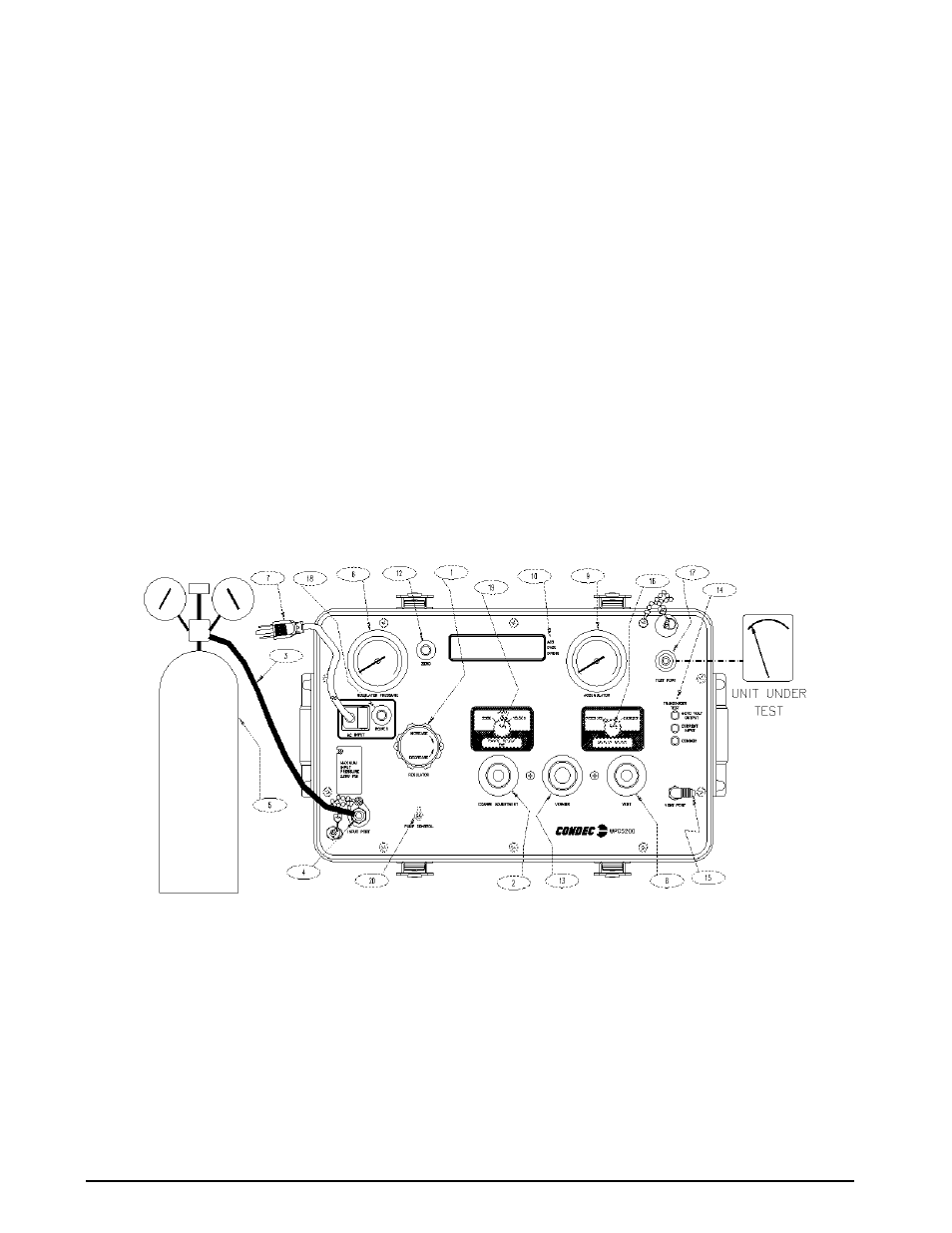
Figure 2-2. Pressure Measurement Sequence (Gage Only)
NOTE: UPC5200 shown, AC Input (7) and Input Port (4) are on back side of UPC5210 Rack Mountable Calibrator.
2.4
Pressure Measurement Sequence (Absolute Only)
NOTE: See Figure 2-3 on page 8, when following these steps.
1. Note that the indicator on the right end of the display indicates ABSOLUTE mode (10).
2. If only pressure measurements greater than barometric are required, continue to step 2.1. If pressure
measurements below atmospheric pressure are required go to step 3.
2.1.
UPC5200: Open the cylinder valve (5) by rotating counter-clockwise slowly until it stops.
UPC5210: Open the pressure source valve (customer supplied).