Condec UPC5210 User Manual
Page 14
Calibration
11
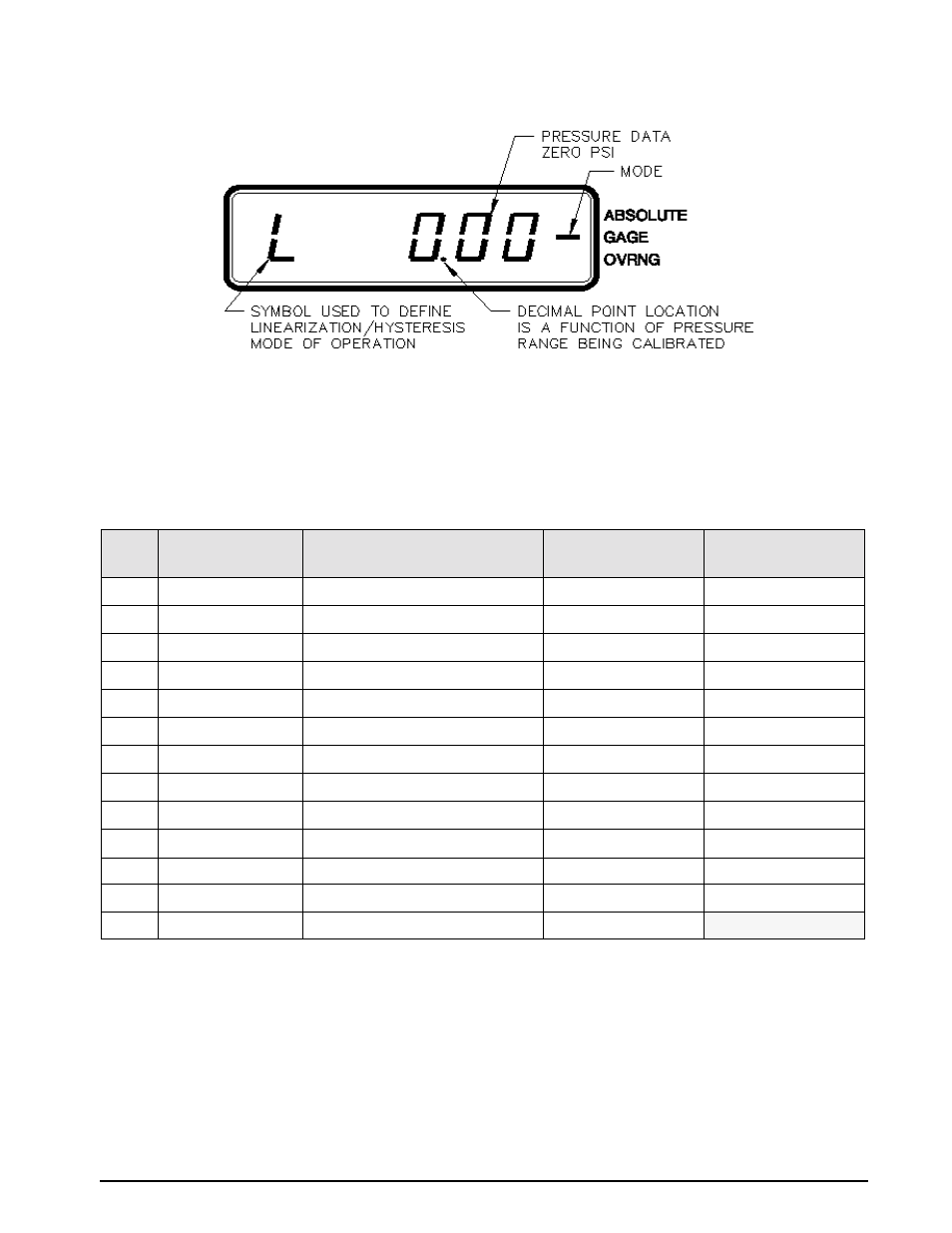
Figure 3-3. Linearity and Hysteresis Calibration
Starting with the instrument's lowest pressure range, sequentially perform the thirteen steps described in
Table 3-2, for each pressure range being calibrated. Perform the following for each step:
1. Adjust input pressure to the appropriate value without overshooting the setting. If value is overshot by
more than 1%, vent unit and repeat steps.
2. Perform the action as indicated when the readings are stable. Should not take longer than 15 minutes. If
it takes longer, check system for leaks. If no leaks are found, the CPU or transducer may be defective.
When step no. 11 is reached, the display changes so that the left most status symbol is
H
. This remains for step 12
and down to approximately 0.00 PSI.
NOTES:
1. If reading is in motion or correction required is not within ±0.8% of Full-Scale, no entry is made.
2. If entry is valid, the display momentarily indicates the correction value (in percent) and the memory location
at which it is stored.
3. If 100% ±0.05% is not obtained, repeat the Zero/Span calibration sequence.
4. Absolute only unit: Maximum PSIA test standard display reading of 0.05 PSIA.
STEP
NO.
INPUT PRESSURE %
OF RANGE
OPERATOR ACTION REQUIRED
STATUS SYMBOL IN
LEFT MOST DIGIT
REMARKS
1
0 (Note 4 below)
Press
ZERO
Switch
L
Zero on Display
2
10
Press
ENTER
button
L
Notes 1 & 2 below
3
20
Press
ENTER
button
L
Notes 1 & 2 below
4
30
Press
ENTER
button
L
Notes 1 & 2 below
5
40
Press
ENTER
button
L
Notes 1 & 2 below
6
50
Press
ENTER
button
L
Notes 1 & 2 below
7
60
Press
ENTER
button
L
Notes 1 & 2 below
8
70
Press
ENTER
button
L
Notes 1 & 2 below
9
80
Press
ENTER
button
L
Notes 1 & 2 below
10
90
Press
ENTER
button
L
Notes 1 & 2 below
11
100
No Action Required
H
Note 3 below
12
50
Press
ENTER
button
H
Notes 1 & 2 below
13
0 (Note 4 below)
No Action Required
L
Table 3-2. Linearization and Hysteresis Calibration Sequence