3 pressure measurement sequence (gage only) – Condec UPC5210 User Manual
Page 8
Operation
5
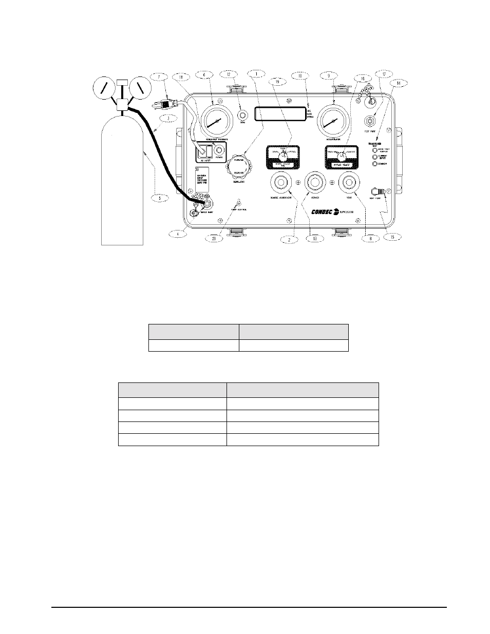
Figure 2-1. Initial Setup Procedure
NOTE: UPC5200 shown, AC Input (7) and Input Port (4) are on back side of UPC5210 Rack Mountable Calibrator.
9. Optional - if the current (4.000 to 20.000 mA) measurement features are to be used, connect the
provided Transducer Test Cable (PN 55092) to the Transducer Test Jacks (14).
When connected, this cable provides +28 VDC excitation. The internal impedance (load) is 10 ohms. The display
scaling for these current measurements are as follows:
The test cable connector wiring is as follows:
NOTE: Connector pin designations are for reference only, and are no longer a connector on newer units. See Figure 2-1
on page 5 (14).
2.3
Pressure Measurement Sequence (Gage Only)
NOTE: See Figure 2-2 on page 6, when following these steps.
1. Note that the indicator on the right end of the display indicates GAGE mode (10).
2. Zero unit by depressing the
ZERO
switch (12) for less than five seconds. The instrument can be zeroed at
any time, as long as the VENT valve (8) is open, by depressing the
ZERO
switch (12).
NOTE: If ZERO switch is depressed longer than 5 seconds unit will perform an internal, functional self-check.
3. UPC5200: Open the cylinder valve (5) by rotating counter-clockwise slowly until it stops.
UPC5210: Open the, customer supplied, pressure source valve.
SWITCH POSITION
DISPLAY READING
Current
0-20.000 mA by 0.005 mA
Table 2-1. Display Select Switch (16)
CONNECTOR PIN DESIGNATION
FUNCTION
A
+ VDC
B
+ SIGNAL
C
NOT USED
D
VOLTAGE & SIGNAL COMMON
Table 2-2. Transducer Test Cable (PN 55092)