5 shunt resistor calibration, 6 current input calibration, 7 permanent data storage – Condec UPC5210 User Manual
Page 15
12
UPC5200/UPC5210 Operation and Maintenance Manual
3.5
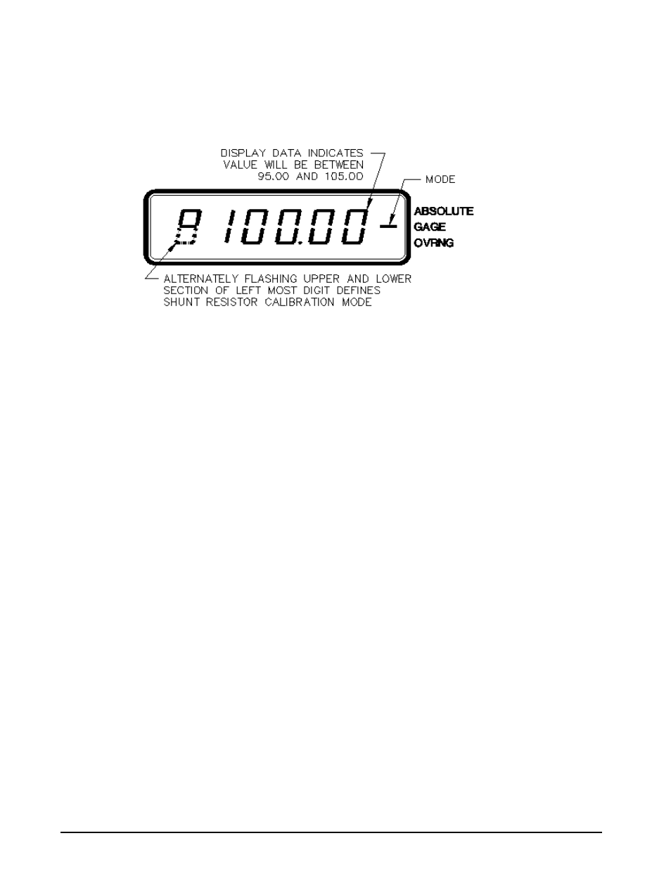
Shunt Resistor Calibration
Install the Condec Calibration Module (PN 60109) and select the SHUNT position of the rotary switch on the
module. This places the UPC5200/UPC5210 into its SHUNT RESISTOR calibration mode. The display is
shown in Figure 3-4.
Figure 3-4. Shunt Resistor Calibration
With the UPC5200/UPC5210's highest pressure range selected, perform the four step sequence described below:
1. Gage Only Units: Be sure the input pressure to the UPC5200/UPC5210 is at 0 PSIG.
NOTE: Absolute Only Units: Must use a vacuum pump with PSIA test standard, to reach as close to 0 PSIA as
possible (maximum PSIA test standard display reading of 0.05 PSIA).
2. Press and hold the
ZERO
button on the Condec Calibration Module until a stable zero indication is
obtained.
3. Release the
ZERO
button and allow the display to stabilize at its shunt resistor calibration number.
(100 ± 5.00%)
4. Press the
ENTER
button on the Condec Calibration Module. When accepted, the bottom half of all
display digits are momentarily illuminated.
3.6
Current Input Calibration
To calibrate the current input, a current generator capable of generating 20 mA must be connected to the
COMMON and CURRENT INPUT jacks, see Figure 2.2 on page 4 (14). The DISPLAY SELECT switch (16)
should be on the CURRENT position.
1. Set the Condec Calibration Module (PN 60109) to the ZERO/SPAN position. The display is similar to
Figure 3-2 on page 10.
2. Press the
ZERO
button on the module. The display reads
0.00
.
3. Set the Current Generator for 20 mA output. Press the
ENTER
button on the module. The display should
read
20.00
.
NOTE: If the display reading is off, set the Current Generator to 0, and press the ENTER button on the Condec
Calibration Module. Set the Current Generator for 20 mA output. The display reads 20.000. If the display
reading is off, press the
ENTER
button on the module. If the display reading is not 20.000, CPU is faulty and
requires servicing.
4. Disconnect the current generator.
3.7
Permanent Data Storage
After completing the above calibration procedures, the new data that has been entered into the computer must be
permanently stored. The sequence to do this is as follows:
1. Select the DATA RECALL position of the rotary switch on the Condec
Calibration Module, (PN 60109).
2. Press the
STORE
pushbutton on the module.
3. If the data is accepted, the four-digit number on the right side of the display indicates
1 020
for as long as
the
STORE
button is pressed.