2 geo s12 general set-up instructions, 1 speaker connection, 1 geo s12 connectors – Nexo LS18 User Manual
Page 11: 2 ls18 connector, 3 configuring geo s12 for passive or active mode, 2 geo
GEO
S12
G
ENERAL
S
ET
-
UP
I
NSTRUCTIONS
Page 11/103
2 GEO
S12
G
ENERAL
S
ET
-
UP
I
NSTRUCTIONS
2.1 Speaker connection
GEO S12 and LS18 is connected with Speakon NL4FC plugs (not supplied). A wiring diagram is printed
on the connection panel located on the back of each cabinet. The 4 pins of the 2 Speakon sockets
identified in / out are connected in parallel within the enclosure.
Either connector can be used to connect amplifier or to link to an additional Geo S12 cabinet or to link to
an optional LS18 (if present). Therefore, a single 4-conductor cable can connect two amplifier channels
to various Geo S12 and/or Sub Bass.
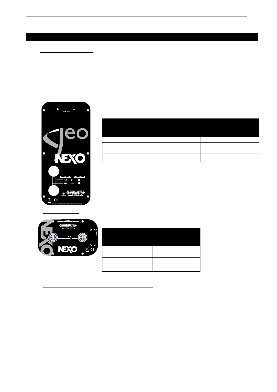
2.1.1 GEO S12 connectors
Connectors are wired as follows:
2.1.2 LS18 connector
Connectors are wired as follows:
2.1.3 Configuring Geo S12 for Passive or Active Mode
Remove the six TORX screws that hold the connector panel (figure next page);
Remove the connector panel so that filter WAGO connectors become accessible;
In Passive Mode, connector A (from filter) should be inserted in connector B (PCB
“Passive In”), and Connector D (“Passive Out”) should be connected to speakers via
connector C.
In Active Mode, WAGO Connector A (from filter) should be directly connected into
speakers via connector C (PCB connectors B & D are then unused).
Speakon
Connector
Passive
Mode
Active
Mode
1(-)
Not Connected
Geo S12 LF (-)
1(+)
Not Connected
Geo S12 LF (+)
2(-)
Geo S12 (-)
Geo S12 HF (-)
2(+)
Geo S12 (+)
Geo S12 HF (+)
Speakon
Connector
1(-)
LS18 (-)
1(+)
LS18 (+)
2(-)
Not Connected
2(+)
Not Connected