Sterling QVSD User Manual
Page 9
9
INSTALLATION (Continued)
THERMOSTAT WIRING AND LOCATION
NOTICE: The thermostat must be mounted on a
vertical, vibration-free surface, free from air currents,
and in accordance with the furnished instructions.
Mount the thermostat approximately 5 feet (1.5m) above
the fl oor, in an area where it will be exposed to a free
circulation of average temperature air. Always refer to the
thermostat instructions, as well as our unit wiring
diagram, and wire accordingly. Avoid mounting the
thermostat in the following locations:
1. Cold Areas- Outside walls or areas where drafts may
affect the operation of the control.
2. Hot Areas- Areas where the sun’s rays, radiation, or
warm air currents may affect the operation of the
control.
3. Dead Areas- Areas where the air cannot circulate
freely, such as behind doors or in corners.
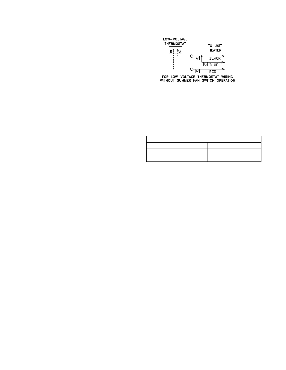
NOTICE: Thermostat wires tagged “W” and “G” must
be connected together except when using a general
purpose “SPDT” 24VAC relay and standard
thermostat with a subbase, or when using a
Honeywell T834H or T834N thermostat. Also refer to
Figure 5 for other wiring connections.
Figure 5 - C1267G
THERMOSTAT HEAT ANTICIPATOR ADJUSTMENTS
The initial heat anticipator setpoint should equal the
thermostat’s current amperage draw when the unit is
firing. This setpoint should be measured for the best
results. Use the recommended ranges for a guide. If
further information is needed, consult your thermostat
manufacturer’s instructions.
Recommended heat anticipator setting ranges:
25 feet (7.6m) T'stat wiring
50 feet T'stat wiring
0.85 to 0.90 A
0.90 to 1.1 A Max.
setting
on
t'stat