21 operation – Sterling QVSD User Manual
Page 21
21
OPERATION
Never operate the unit beyond the
specified limits or severe damage to, and/or
premature failure of, the unit will result!
EXPLANATION OF CONTROLS
1. Each Separated Combustion Duct Furnace comes
equipped with a power vent system that consists of a
power ventor motor and blower, pressure switch, and
sealed fl ue collector. (See Figure 15)
The addition of external draft hoods
or power ventors is not permitted. Addition of such
devices may cause serious unit malfunction or
failure.
2. The power ventor is energized by the room thermostat
when a demand for heat is sensed. The pressure
switch measures the differential pressure between
the air inlet and the exhaust vent systems. If the
differential is correct, the indirect spark ignition
system is energized.
Under no circumstances is the
unit to be fi red if the power ventor is not operable,
or severe personal injury or death may occur!
3. The indirect spark ignition system consists of an
ignition module, a dual combination gas valve, and a
spark-ignited pilot burner. When the pressure switch
is closed, the pilot valve opens as a spark is generated
to light the pilot. When the fl ame is sensed by the
fl ame sensing circuit, the spark ceases, and the main
gas valve opens to supply gas to the main burners.
Once the thermostat is satisfi ed, the vent system and
gas valve are simultaneously de-energized, stopping
all gas fl ow to the unit.
4. The high limit switch interrupts the fl ow of electrical
current to the main gas valve if the duct furnace
becomes overheated.
5. The optional fan switch delays the operation of the
fan for approximately 45 seconds once the thermostat
is closed, and continues fan operation for
approximately 65 seconds after the thermostat opens.
The start-up fan delay must not exceed 90 seconds
from a cold start.
6. The wall thermostat, supplied optionally, is a
temperature sensitive switch that operates the vent
and ignition systems to control the temperature of
the space being heated.
NOTICE: The thermostat must be mounted on a
vertical, vibration-free surface, free from air currents,
and in accordance with the furnished instructions.
INITIAL LIGHTING
1. Open the manual gas valve, in the gas supply line to
the duct furnace. Loosen the union in the gas supply
line to purge it of air. Tighten the union, and check for
leaks.
NOTICE: Check all pipe joints for leakage using a soap
solution or other approved method.
Never use an open fl ame to detect
gas leaks. Explosive conditions may exist which
could result in property damage, personal injury
or death.
Before attempting to light or
relight the pilot, wait 5 minutes to allow gas
which may have accumulated in the burner
compartment to escape. Failure to heed this
warning could result in property damage,
personal injury or death!
2. Turn on electrical power. The duct furnace should now
be under the control of the thermostat. Set the
thermostat to it's highest setting, the power ventor
motor should start, and burner ignition occur. Turn
the thermostat to the lowest setting. The burners and
power ventor should stop operating immediately.
Reset the thermostat to the desired operational
setting.
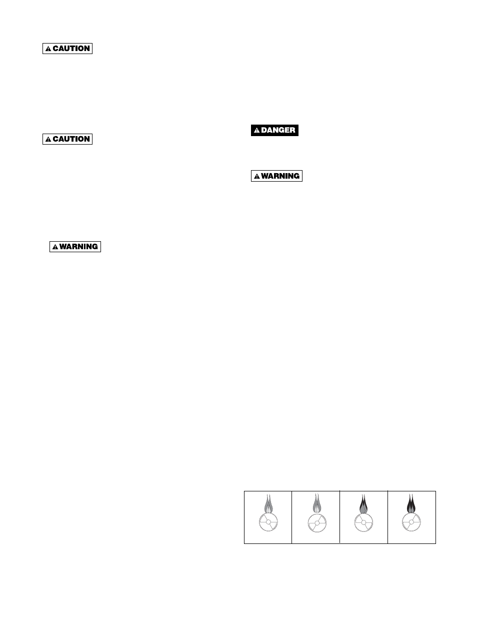
PRIMARY AIR SHUTTER ADJUSTMENT
After the unit has been operating for at least 15 minutes,
adjust the primary air flow to the burners. Turn the
friction-locked, manually-rotated air shutters clockwise to
close, and counterclockwise to open.
For correct air adjustment, close the shutter until yellow
tips in the fl ame appear. Then, open the air shutter to the
point just beyond where the yellow tipping disappears.
Refer to Figure 12.
NOTICE: There may be momentary and spasmodic
orange fl ashes in the fl ame. This is caused by the
burning of airborne dust particles, and should not
be confused with yellow tipping, which is a stable, or
permanent, situation when there is insufficient
primary air.
Figure 12 - Main Burner Flames
SHUT DOWN
1. Turn the valve selector knob to the "OFF" position.
2. Turn off the electricity.
3. To relight, follow "Initial Lighting" instructions.
NORMAL
(HARD FLAME)
LIFTING
(TOO MUCH AIR)
YELLOW TIPPING
(MARGINAL)
YELLOW FLAME
(TOO LITTLE AIR)