8installation (continued) – Sterling QVSD User Manual
Page 8
8
INSTALLATION (Continued)
MAKE CERTAIN THAT THE STRUCTURE TO WHICH THE FURNACE IS TO BE
MOUNTED IS CAPABLE OF SAFELY SUPPORTING ITS WEIGHT. UNDER NO
CIRCUMSTANCES MUST THE GAS LINES, THE VENTING SYSTEM OR THE
ELECTRICAL CONDUIT BE USED TO SUPPORT THE HEATER; OR SHOULD ANY
OTHER OBJECTS (I.E. LADDER, PERSON) LEAN AGAINST THE HEATER, GAS
LINES, VENTING SYSTEM OR ELECTRICAL CONDUIT FOR SUPPORT. FAILURE
TO HEED THESE WARNINGS MAY RESULT IN PROPERTY DAMAGE, PERSONAL
INJURY OR DEATH.
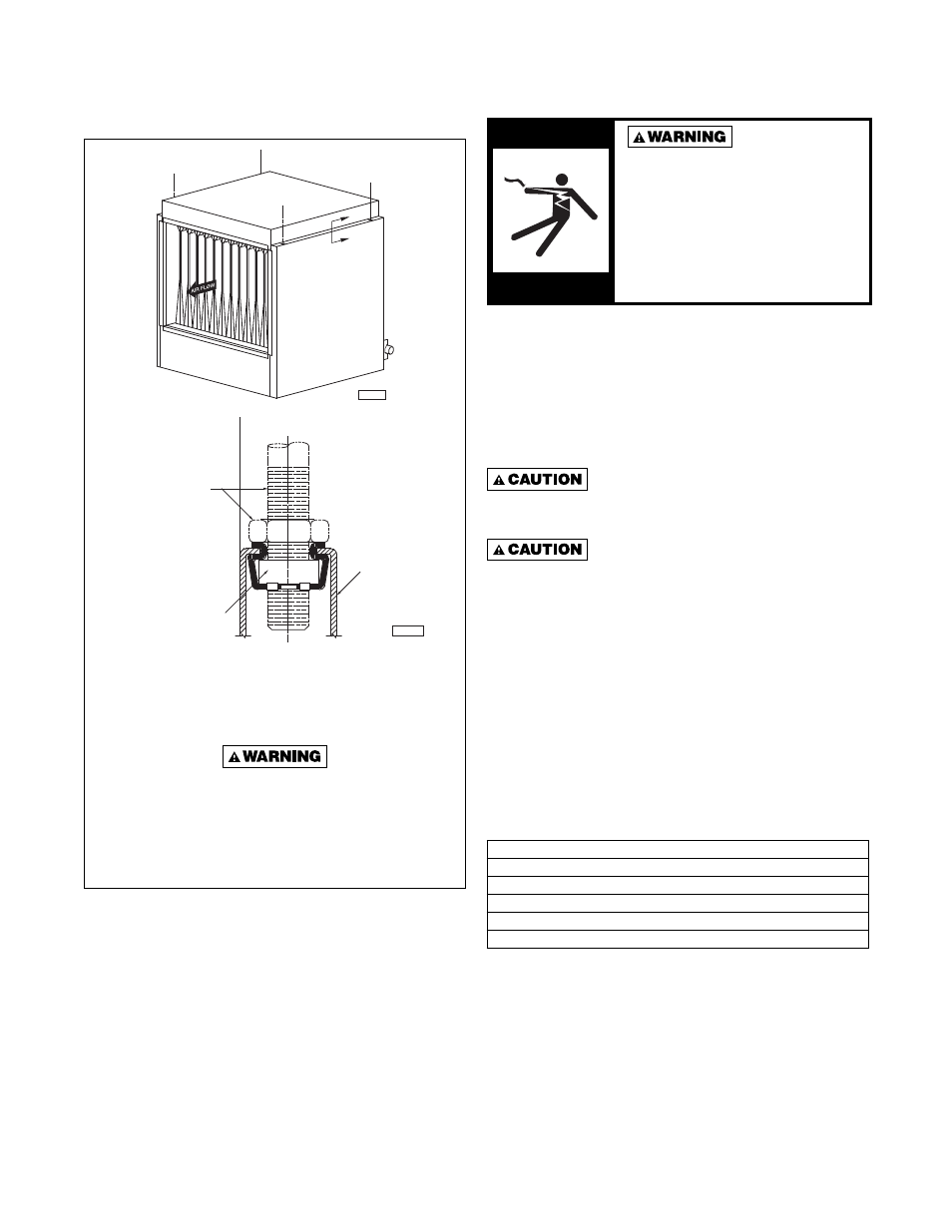
3/8-16 Treaded
Suspension Rod &
Jam Nut By Installer
3/8-16 Speed Grip
Nut Retainer
Outside Jacket
Panel (Duct)
D4285
Section “S-S”
Detail Showing Recommended
Method Of Suspension
(Typical)
“S”
“S”
D4284
ELECTRICAL CONNECTIONS
HAZARDOUS VOLTAGE!
disconnect ALL ELECTRIC
POWER INCLUDING REMOTE
DISCONNECTS BEFORE
SERVICING. Failure to
disconnect power before
servicing can cause severe
personal injury or death.
Standard units are shipped for use on 115 volt, 60 hertz,
single phase electric power. The motor name-plate and
electrical rating of the transformer should be checked
before energizing the duct furnace electrical system. All
external wiring must conform to the latest edition of ANSI/
NFPA No. 70, National Electrical Code, and applicable
local codes; in Canada, to the Canadian Electrical Code,
Part 1, CSA Standard C22.1
Do not use any tools (i.e. screwdriver,
pliers, etc.) across the terminals to check for power.
Use a voltmeter.
USE COPPER CONDUCTORS ONLY!
UNIT TERMINALS ARE NOT DESIGNED TO ACCEPT
OTHER TYPES OF CONDUCTORS. Failure to do so
may cause damage to the equipment
It is recommended that the electrical power supply to each
duct furnace be provided by a separate, fused, and
permanently live electrical circuit. A disconnect switch of
suitable electrical rating should be located as close to
the gas valve as possible. Each duct furnace must be
electrically grounded in accordance with the latest edition
of the National Electrical Code, ANSI/NFPA No. 70, or
CSA Standard C22.1 Sample wiring diagrams are shown
in Figures 6, and 7.
Table 4 - Full Load Current In Amperes
Ampere Values Apply to All Unit Capacities
Amps at 115 Volts
1.9
Amps at 208 Volts
1.1
Amps at 230 Volts
1.0
Amps at 460 Volts
0.5
Amps at 575 Volts
0.4
Figure 4 - Typical Four Point Duct Suspending
Arrangement