Sterling QVSD User Manual
Page 22
22
2. Turn off the manual gas valve and electrical power to
the duct furnace.
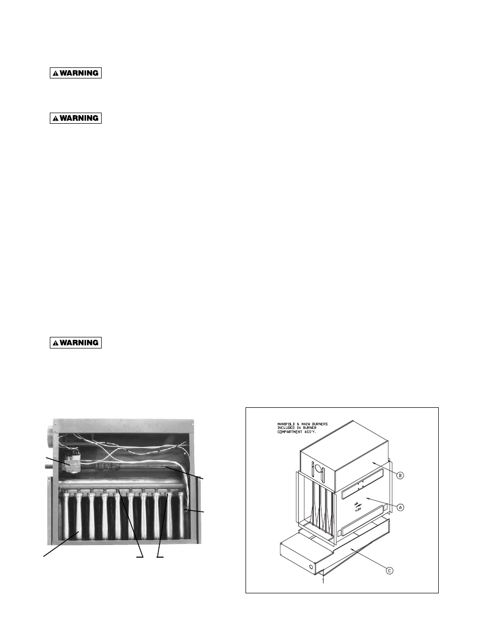
3. To clean or replace the main burners, open the bottom
panel and compress the spring by moving the burner
toward the manifold. Slide the opposite end of the
burner downward from the locating slot while retaining
spring is still compressed. Pull the burners away from
the heater.
4. With the burners removed, wire brush the inside
surfaces of the heat exchanger.
5. Remove any dirt, dust, or other foreign matter from
the burners using a wire brush and/or compressed
air. Ensure that all parts are unobstructed. Inspect
and clean the pilot burner if necessary.
6. Reassemble the gas duct furnace by replacing all
parts in reverse order.
7. Complete the appropriate unit start-up procedure as
given in the “Operation” section of this manual (see
unit lighting instruction plate and the unit nameplate).
8. Check the burner adjustment. See “Primary Air
Shutter Adjustment” section in this manual.
9. Check all gas control valves and pipe connections
for leaks.
10. Check the operation of the automatic gas valve by
lowering the setting of the thermostat, stopping the
operation of the gas duct furnace. The gas valve
should close tightly, completely extinguishing the
fl ame on the main burners.
11. Inspect and service the blower section of the system.
12. Check and test the operational functions of all safety
devices supplied with your unit.
MAINTENANCE
PERIODIC SERVICE
Open all disconnect switches and
secure in that position before servicing unit.
Failure to do so may result in personal injury or
death from electrical shock!
Gas tightness of the safety shut-
off valves must be checked on at least an annual
basis.
To check gas tightness of the safety shut-off valves, turn
off the manual valve upstream of the appliance
combination control. Remove the 1/8 inch pipe plug on the
inlet side of the combination control and connect a
manometer to that tapping. Turn the manual valve on to
apply pressure to the combination control. Note the
pressure reading on the manometer, then turn the valve
off. A loss of pressure indicates a leak. If a leak is detected,
use a soap solution to check all threaded connections. If
no leak is found, combination control is faulty and must be
replaced before putting appliance back in service.
NOTICE: The heater and vent system should be
checked once a year by a qualifi ed technician.
Should maintenance be required, perform the following
inspection and service routine:
1. Inspect the area near the unit to be sure that there is
no combustible material located within the minimum
clearance requirements listed in Table 3.
Under no circumstances should
combustible material be located within the
clearances specifi ed in Table 3. Failure to provide
proper clearances could result in personal injury
or equipment damage from fi re!
Figure 14 - Internal Furnace Assembly
Figure 13 - Combustion Chamber
MANIFOLD
PILOT ASSY.
RETAINER SPRING
AIR SHUTTERS
GAS VALVE
MAIN
BURNERS