Sterling QVSD User Manual
Page 23
23
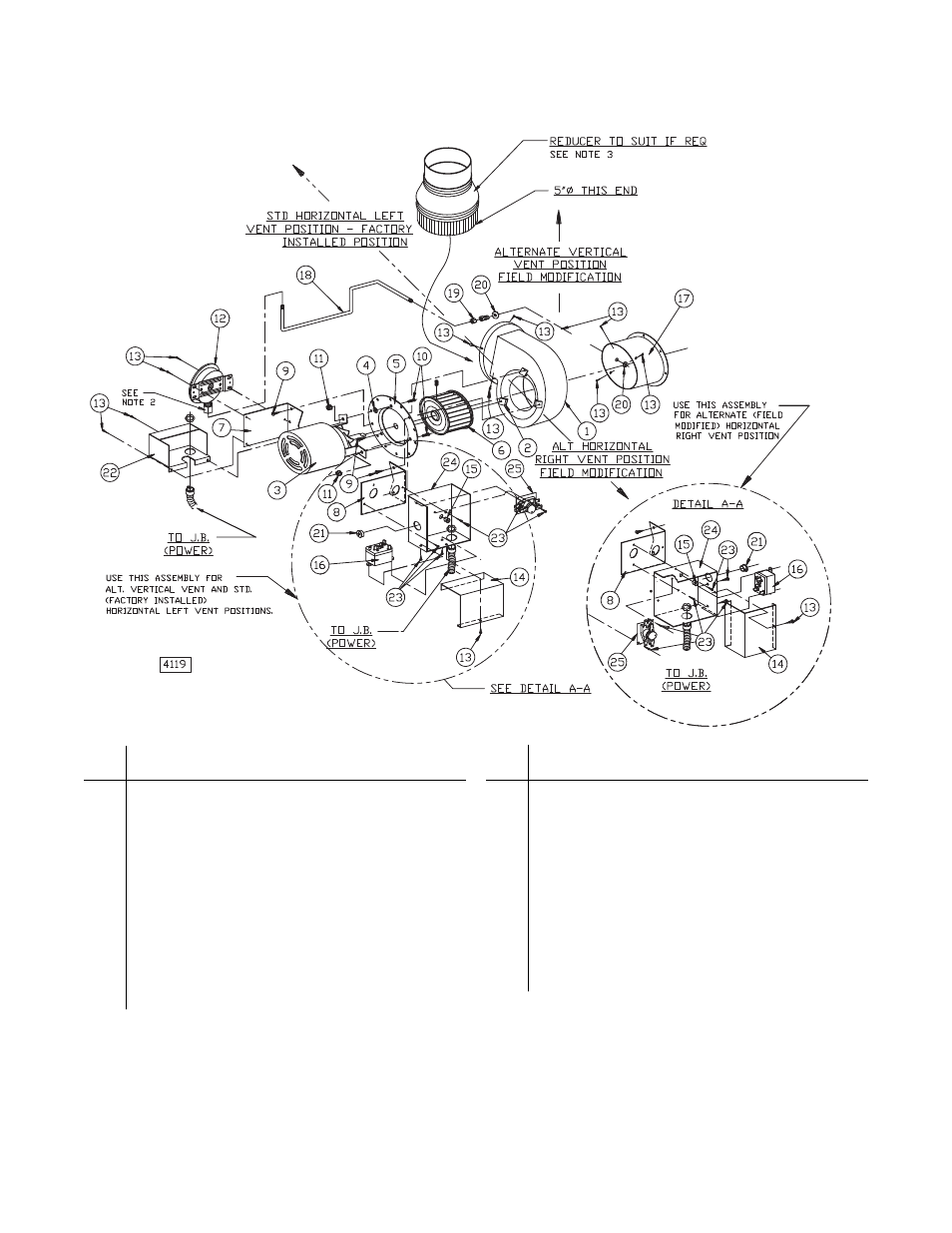
Figure 15 - Power Venter Assembly
Ref.
No. Description
1
Blower Housing Assembly
2
Speed Nut
3
Motor
4
Washer, Plain
5
Plate Adapter
6
Blower Wheel
7
Mounting Bracket (Pressure Switch)
8
Mounting Bracket (Junction Box)
9
Screw, S.T.
10
Screw, Machine (L =
3
/
4
inch)
11
Nut, Keps (Ext. Lock Washer)
12
Air Pressure Switch*
13 Drill
Screw
Ref.
No. Description
14
Junction Box Cover
15 Snap
Bushing
16 Relay
(Motor)
17
Draftor Stack Assembly
18
Tubing (Aluminum) Formation
19 Male
Connector
20 Locknut
21 Hole
Plug
22
Pressure Switch Cover
23 Drill
Screw
24
Junction Box Base
25 Relay
(Purge)
NOTES:
*1) For item No. 6 use counter-clockwise rotation.
2) DO NOT OVERTIGHTEN CELCON NUT! HAND TIGHTEN ONLY! DO NOT USE TOOLS!
Approximate 1/3 turn maximum or 8 inch pounds is suffi cient from the point where the tube does not slip in or out.
3) Flue Sizes:
100/175 units: 4 inch diameter fl ue outlet Reducer required – To be supplied by installer.
200/250 units: 5 inch diameter fl ue outlet (no adaptor required on fl ue).
300/400 units: 6 inch diameter fl ue outlet Increaser required – To be supplied by manufacturer.
4) See “Power Vent Position” in Installation section for instructions on how to adjust vent position from factory installed position.