Installation (continued) – Sterling TD User Manual
Page 8
8
INSTALLATION (continued)
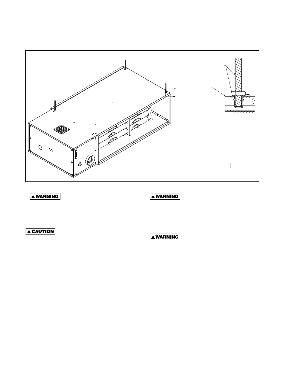
SUSPENSION
Figure 5 - Typical Suspension
Ensure that all hardware used in
the suspension of each duct furnace is more than
adequate for the job. Failure to do so may result
in extensive property damage, personal injury or
death.
The duct furnace must be hung level
from side to side and front to back, from four
suspension points provided at the top of the unit.
Failure to do so will result in poor performance and/
or premature failure of the unit. Refer to Figure 5 for
typical suspension. DO NOT mount duct furnaces in
series (one in front of another).
NOTICE: Minimum safety clearances must also be
maintained; see Table 3. When service/accessibility
clearances are greater than minimum safety
clearances, service/accessibility clearances take
precedence. See “Clearances” section under
“Installation.”
Make cer tain that the lifting
methods used to lift the duct furnace are capable
of supporting the weight of the heater during
installation. Failure to heed this warning may
result in property damage or personal injury. See
Table 1 for unit weights.
Make certain that the structure to
which the duct furnace is to be mounted is
capable of safely supporting its weight. Under
no circumstances must the gas lines, venting
system, or the electrical conduit be used
to support the duct furnace or any other objects
(i.e. ladder, person) lean against the gas lines,
venting system, or electrical conduit for support.
Failure to heed these warnings may result in
property damage, personal injury, or death.
SECTION A-A
SCALE 1:1
A
A
D9376
AIR
FL
OW
←
3/8" THREADED SUSPENSION ROD
& JAM NUT BY INSTALLER
OUTSIDE JACKET
PANEL (UNIT)
D9376