Sterling TD User Manual
Page 7
7
INSTALLATION (continued)
DUCTWORK
Properly designed and installed ductwork, providing a
uniformly distributed fl ow of air across all surfaces of the
heat exchanger, is essential to satisfactor y unit
performance and life of the equipment.
All duct connection fl anges/seams must be sealed to
prevent air leaks. Sealant/tape must be suitable for
temperatures of 250°F (121°C) minimum.
Any attempts to straighten the 90°
duct connection fl anges on the duct furnaces will
affect the operation of the furnace and will void
the warranty.
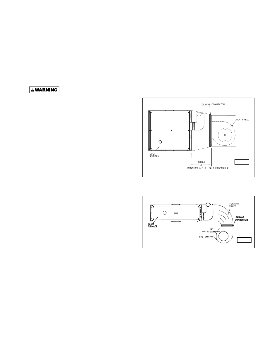
If uniform air distribution is not obtained, install additional
baffl es and/or turning vanes in the ductwork.
Figures 3 and 4 illustrate recommended ductwork designs
for both the straight-through and elbowed air inlet
arrangements.
Access panels large enough to observe smoke and
refl ected light, and to detect the presence of leaks in the
heating equipment, are required both upstream and
downstream from gas duct furnaces. These panels must
be sealed to prevent air leaks. If allowed by local
regulations, install canvas connectors between the
ductwork and fan discharge opening to eliminate the
transmission of mechanical vibration.
AIR FLOW
The installation is to be adjusted to obtain an air
throughput within the range specifi ed on the appliance
rating plate.
COMBUSTION INLET AIR VENTILATION
Inlet Air From Another Room – If the duct furnace is
installed in a separate room or compartment, provide two
inlet air openings. The size of each vent opening should
be no less than one square inch (6.452 square centimeters)
of free area for each 1000 Btu/hr. (293 W) input. Each
opening must not be less than 100 square inches (645
square centimeters).
Inlet Air From Outdoors – If the enclosed space is
to have inlet combustion air from the outside, the vent
opening should be no less than one square inch
(6.452 square centimeters) of free area for each
2500-3000 Btu/hr. (733-879 W) input. Each opening must
not be less than 100 square inches (645 square
centimeters).
BYPASS
When a gas duct furnace is installed to operate in
conjunction with a summer air conditioning system, the
CFM air delivery of the system blower should be adjusted
to meet the design air volume requirements for cooling.
If this CFM delivery is greater than that required for
heating, resulting in a low air temperature rise, install a
damper bypass around the gas duct furnace to bypass a
portion of the air.
Figure 3 - Recommended Ductwork Design for
Straight-Through Arrangement
Figure 4 - Recommended Ductwork Design
for Elbowed Arrangement
D9382
D9381