Installation (continued) – Sterling TD User Manual
Page 11
11
INSTALLATION (continued)
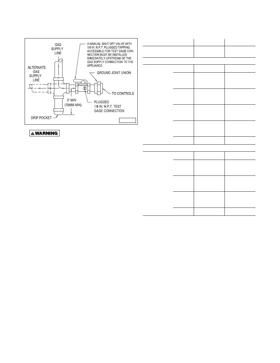
Figure 6 - Pipe Installation, Standard Controls
Never use an open fl ame to detect
gas leaks. Explosive conditions may exist which
may result in personal injury or death!
The appliance and its individual shutoff valve must be
disconnected from the gas supply piping system during
any pressure testing of that system in excess of 1/2 psig
(3.5 kPa).
The appliance must be isolated from the gas supply piping
system by closing its individual manual shutoff valve
during any pressure testing of the gas supply piping
system at test pressures equal to or less than 1/2 psig
(3.5 kPa).
Table 5 - Gas Supply Pressure*
Natural Gas
Propane Gas
Heating Value
1,050 BTU/Ft
3
(39.1 MJ/m
3
)
2,500 BTU/Ft
3
(93.1 MJ/m
3
)
Manifold Pressure
Single Stage
Application
(inch WC)
(kPa)
3.5
(0.87)
10.0
(2.49)
Two Stage
Application -
High Fire
(inch WC)
(kPa)
3.5
(0.87)
10.0
(2.49)
Two Stage
Application -
Low Fire
(inch WC)
(kPa)
1.1
(0.27)
3.8
(0.95)
Modulating
Application -
High Fire
(inch WC)
(kPa)
3.5
(0.87)
10.0
(2.49)
Modulating
Application -
Low Fire
(inch WC)
(kPa)
0.9
(0.22)
3.5
(0.87)
Minimum Supply Pressure
Single Stage
Application
(inch WC)
(kPa)
5.0
(1.24)
11.0
(2.74)
Two Stage
Application
(inch WC)
(kPa)
6.5
(1.62)
11.5
(2.86)
Modulating
Application
(inch WC)
(kPa)
6.5
(1.62)
11.5
(2.86)
Maximum
Supply
Pressure
(inch WC)
(kPa)
14.0
(3.49)
14.0
(3.49)
* Applicable for units installed at or below 2,000 feet (610m) altitude.
See High Altitude Deration information for altitudes greater than
2,000 feet (610m).
D3631C